Basin-type insulator surface coating curing device

A basin-type insulator, surface coating technology, applied in the direction of surface coating liquid device, coating, pretreatment surface, etc., can solve the problems of surface coating coating flow, accumulation, etc., to facilitate fixed installation, reduce The overall height and the effect of weakening the flow

Active Publication Date: 2021-07-27
PINGGAO GRP +3
View PDF2 Cites 0 Cited by
  • Summary
  • Abstract
  • Description
  • Claims
  • Application Information

AI Technical Summary

Problems solved by technology

[0005] The purpose of the present invention is to provide a surface coating curing device for basin-type insulators to solve the technical problem that the surface coating of basin-type insulators in the prior art tends to flow and accumulate during the curing process

Method used


Image

  • Basin-type insulator surface coating curing device
  • Basin-type insulator surface coating curing device
  • Basin-type insulator surface coating curing device

Examples


Embodiment 1

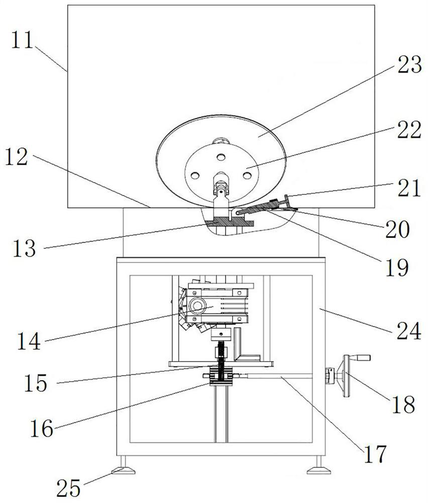
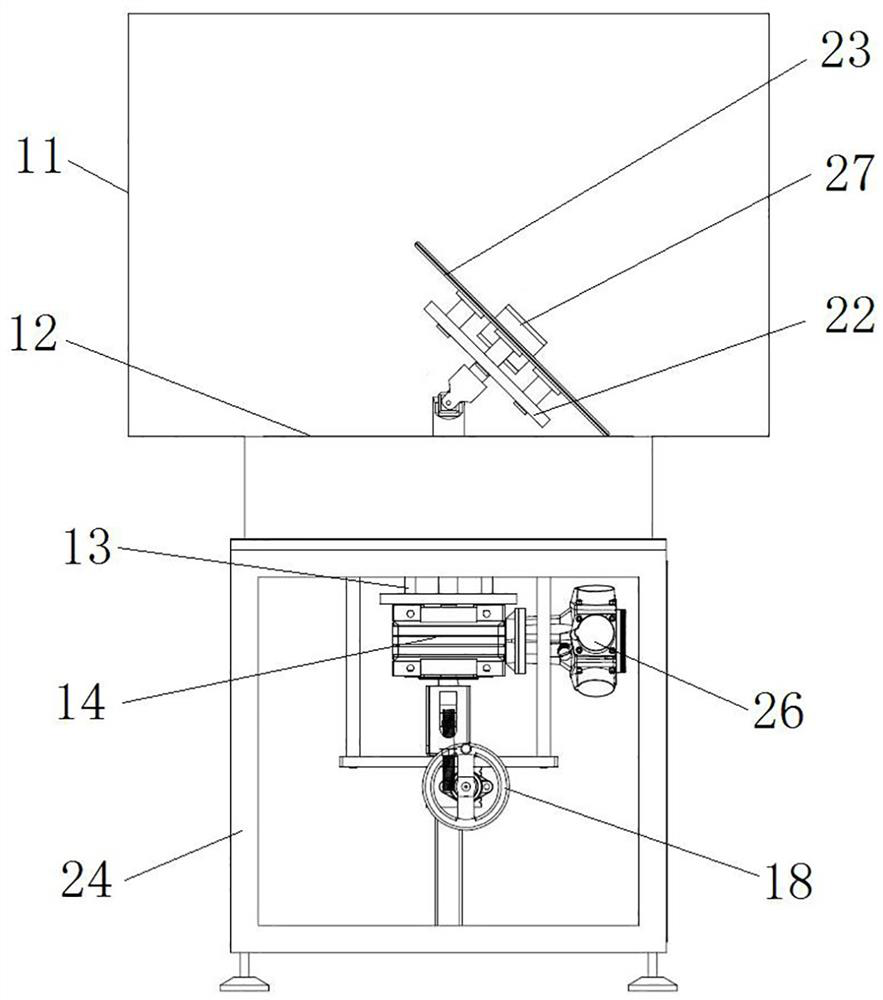
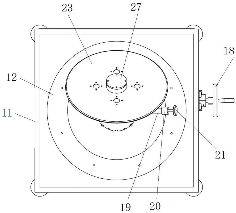
[0041] Such as Figure 1 to Figure 3 As shown, the basin-type insulator surface coating curing device includes a frame body 24 and an oven 11, the frame body 24 has a support platform 12, and the support platform 12 is provided with perforations; the oven 11 is fixed on the support platform 12, and the oven 11 and perforated connection.

[0042] In this embodiment, the frame body 24 has a box structure as a whole, and an air motor 26, a worm gear reducer 14, and a turret 13 are arranged inside the frame body 24, and the turret 13 is located above the worm gear reducer 14, and the air motor 26 On one side of the worm gear reducer 14 in the horizontal direction, the air motor 26 drives the turret 13 to rotate through the worm reducer 14 , and the rotation axis of the turret 13 is a vertical axis. Among them, the air motor 26 constitutes the drive device. In other embodiments, the air motor may be replaced by an electric motor.

[0043] In this embodiment, the lower part of th...

Embodiment 2

[0056] The difference between this embodiment and Embodiment 1 is that in Embodiment 1, the turret 13 can be lifted up and down in the vertical direction, so as to be suitable for pot insulators of different sizes. In this embodiment, the turret cannot be raised and lowered in the vertical direction, and at this time, the curing device is only suitable for pot insulators of one size.

Embodiment 3

[0058] The difference between this embodiment and Embodiment 1 is that in Embodiment 1, a worm gear transmission mechanism is provided on the frame body 24. The worm gear transmission mechanism includes a worm wheel 16 and a worm screw 15. 16 is engaged to drive the turret 13 to lift. In this embodiment, a driving cylinder is provided on the frame body, and the driving end of the driving cylinder is used to drive the rotating part to go up and down.


PUM


Abstract

The invention relates to a basin-type insulator surface coating curing device. The basin-type insulator surface coating curing device comprises a frame body, a drying oven, a rotating frame, a workpiece fixing disc and a power rod, the frame body is provided with a supporting platform, and the supporting platform is provided with a through hole; the drying oven is arranged on the supporting platform and communicate with the through hole; the rotating frame is driven by a driving device to rotate, a hinge part is arranged on the rotating frame, and the hinge part penetrates out of the through hole; the workpiece fixing disc is located in the drying oven and used for fixing a basin-type insulator, the workpiece fixing disc is hinged to the hinge part through a universal joint, and one side of the workpiece fixing disc is supported on the upper surface of the supporting platform so that the workpiece fixing disc can be obliquely arranged at a set angle; and one end of the power rod is connected to the rotating frame, and the other end of the power rod drives the workpiece fixing disc to move together when the power rod moves along with the rotating frame. Therefore, the flowing and accumulation of the coating on the concave surface of the basin-type insulator are weakened, the uniformity of the coating on the concave surface of the basin-type insulator is ensured, and the insulating property of the basin-type insulator is improved.

Description

technical field [0001] The invention relates to a coating curing device for surface coating of basin type insulators. Background technique [0002] DC transmission has been widely used due to its advantages of low loss and large transmission capacity. Among them, the DC GIS is an important part of the DC transmission system, and the surface charge accumulation of the pot insulator is an important factor affecting the insulation performance of the DC GIS. [0003] Potty insulators will accumulate surface charges during long-term operation, resulting in a decline in their insulation properties. Coating the surface of the pot insulator can reduce the surface resistivity of the pot insulator, accelerate the dissipation of the surface charge of the pot insulator, and at the same time make the pot insulator have sufficient surface electric strength. [0004] The surface coating of pot insulators generally requires a long curing time and high temperature. Due to the special struc...

Claims


Application Information

Patent Timeline
IPC IPC(8): B05D3/02
CPCB05D3/0272
Inventor 张佩王亚祥郝留成袁端鹏李凯李彩娜陈蕊韩丽娟王满仓涂超丁丁丁刘召召冷龙茂
Owner PINGGAO GRP
Why Eureka
Try Eureka