Mounting and fixing assembly with self-locking structure for chipping machine fly cutter

A technology of self-locking structure and fixing components, which is used in the manufacture of veneer chips, manufacturing tools, wood processing appliances, etc., can solve the problems of high use limitations, impracticality, inconvenient installation of flying knives, etc., and achieves convenient use and precise control. Tilt angle, good use effect

Active Publication Date: 2021-09-21
南京瑞林重工机械制造有限公司
View PDF5 Cites 0 Cited by
  • Summary
  • Abstract
  • Description
  • Claims
  • Application Information

AI Technical Summary

Problems solved by technology

[0002] Chipping machine is also called wood chipping machine, which is one of the series of wood processing equipment. It is widely used in the material preparation section in the production process of textile, papermaking, pulping, wood-based panel and other industries. The main cutting material of this machine is small-diameter wood after peeling. , bamboo, veneer, and leftover wood from felling, etc. The flying knives for chippers generally need to be installed on the chippers and locked by a separate locking structure. The installation structure of the flying knives does not have a self-locking structure and requires additional parts. Lock the flying knife, which makes the installation of the flying knife more inconvenient;
[0003] The applicant also found through research that when the chipper flying knife is used, the angle of the flying knife needs to be adjusted, because most of the installation components connected with the flying knife are fixed structures, and the current chipper flying knife cannot adjust the angle. It is not convenient enough to use the chip machine;
[0004] The applicant also found that the installation structure of the flying knife on the chipper can only be used to install and fix the flying knife with a single hole on the surface, which has high limitations in use, so it is not practical

Method used


Image

  • Mounting and fixing assembly with self-locking structure for chipping machine fly cutter
  • Mounting and fixing assembly with self-locking structure for chipping machine fly cutter
  • Mounting and fixing assembly with self-locking structure for chipping machine fly cutter

Examples


Embodiment Construction

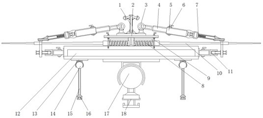
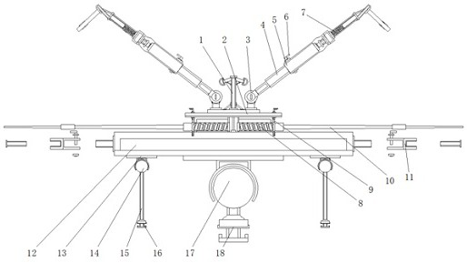
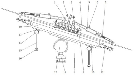
[0031] Such as Figure 1-7 As shown, an installation and fixing assembly with a self-locking structure based on the chipper flying knife includes a baffle frame 1, the lower end of the baffle frame 1 is fixedly equipped with a cutter head lock plate 2, and the top end of the cutter head lock plate 2 Steering shafts 3 are fixedly installed on both sides, and two sets of spherical end buffer structures are arranged on both sides of the top of the baffle frame 1, and the spherical end buffer structures are made of elastic rubber to prevent the two sets of extension rods 4 from turning Collision phenomenon occurs when the shaft rotates, and the safety of the device is high;

[0032] The steering shaft 3 is provided with ring structures on both sides. The fixed end of the bottom side is fixedly connected with the cutter head lock plate 2, and the rotating end of the middle ring is connected with the extension rod 4. The extension rod 4 is a rotating structure, and the extension rod...


PUM


Abstract

The invention provides a mounting and fixing assembly with a self-locking structure for a chipping machine fly cutter. The mounting and fixing assembly comprises a baffle frame, wherein a cutter head locking plate is fixedly mounted at the lower end of the baffle frame, and steering shafts are fixedly mounted on the two sides of the top end of the cutter head locking plate; the outer ends of the steering shafts are connected with extension rods, and rod sleeves are wrapped on outer end openings of the extension rods; cylindrical grooves are formed in the inner sides of the rod sleeves, and the size of the cylindrical grooves is the same as the size of the outer ends of the extension rods; and circular holes which are arranged at equal intervals are formed in the extension rods and the rod sleeves, the connecting positions of the extension rods and the rod sleeves are connected through locking screw rods in a penetrating mode, and side edge locking mechanisms are fixedly mounted at the outer ends of the rod sleeves. According to the mounting and fixing assembly, limiting spring rods and buckling plate strips are arranged so that disc blades which are connected to the cutter head locking plate in a sleeving mode can be limited and locked, and the holes in different positions of the fly cutter can be inserted and locked through the extensible side edge locking mechanisms so that the fixing and using requirements of the fly cutters with different hole models can be met.

Description

technical field [0001] The invention relates to the technical field of chipper equipment, in particular to a mounting and fixing assembly with a self-locking structure for a chipper flying knife. Background technique [0002] Chipping machine is also called wood chipping machine, which is one of the series of wood processing equipment. It is widely used in the material preparation section in the production process of textile, papermaking, pulping, wood-based panel and other industries. The main cutting material of this machine is small-diameter wood after peeling. , bamboo, veneer, and leftover wood from felling, etc. The flying knives for chippers generally need to be installed on the chippers and locked by a separate locking structure. The installation structure of the flying knives does not have a self-locking structure and requires additional parts. Lock the flying knife, which makes the installation of the flying knife more inconvenient; [0003] The applicant also fou...

Claims


Application Information

Patent Timeline
Patent Type & Authority Applications(China)
IPC IPC(8): B27L5/00
CPCB27L5/00
Inventor 武立全
Owner 南京瑞林重工机械制造有限公司
Why Eureka
Try Eureka