
Anti-interception flyer with functions of releasing smoke and bait object and resisting laser impact

A flying object and anti-interception technology, applied in the field of space flight, can solve the problem that the flying object cannot be separated from the air, and achieve the effect of reducing the release

Active Publication Date: 2015-07-22
启东市和洪农副产品专业合作社
View PDF3 Cites 0 Cited by
  • Summary
  • Abstract
  • Description
  • Claims
  • Application Information

AI Technical Summary

Problems solved by technology

[0005] What the present invention aims to solve is the technical problem in the prior art that flying objects in the air cannot be separated after being detected by the detection system, so as to provide an anti-interception device capable of releasing smoke and bait and resisting laser strikes, which can be separated after being detected by the detection system flyer

Method used


Image

  • Anti-interception flyer with functions of releasing smoke and bait object and resisting laser impact
  • Anti-interception flyer with functions of releasing smoke and bait object and resisting laser impact

Examples


Embodiment 1

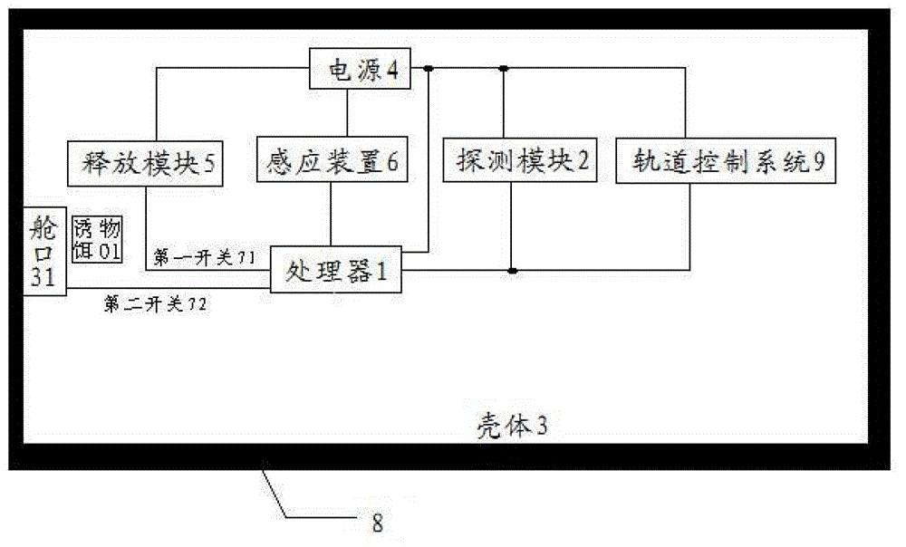
[0034] The structure of the anti-intercepting flying object that releases smoke and bait and resists laser strikes according to the present invention is as follows figure 1 As shown, it includes a processor 1, a detection module 2, a release module 5, a sensing device 6, a housing 3, at least one bait 01, a hatch 31, a protective layer 8, a track control system 9 and a power source 4, among which, The detection module 2 is connected to the processor 1 and is used to perform detection within a preset detection range and send the detection result to the processor 1; the detection module 2 is a radar or a camera. In this embodiment, the detection module 2 is a radar.

[0035] The release module 5 is used to release smoke. The release module 5 is connected to the processor 1 via a first switch 71, and the processor 1 controls the station based on the received detection result of the intercepted object in the predetermined range. The first switch 71 is closed to control the operation ...

Embodiment 2

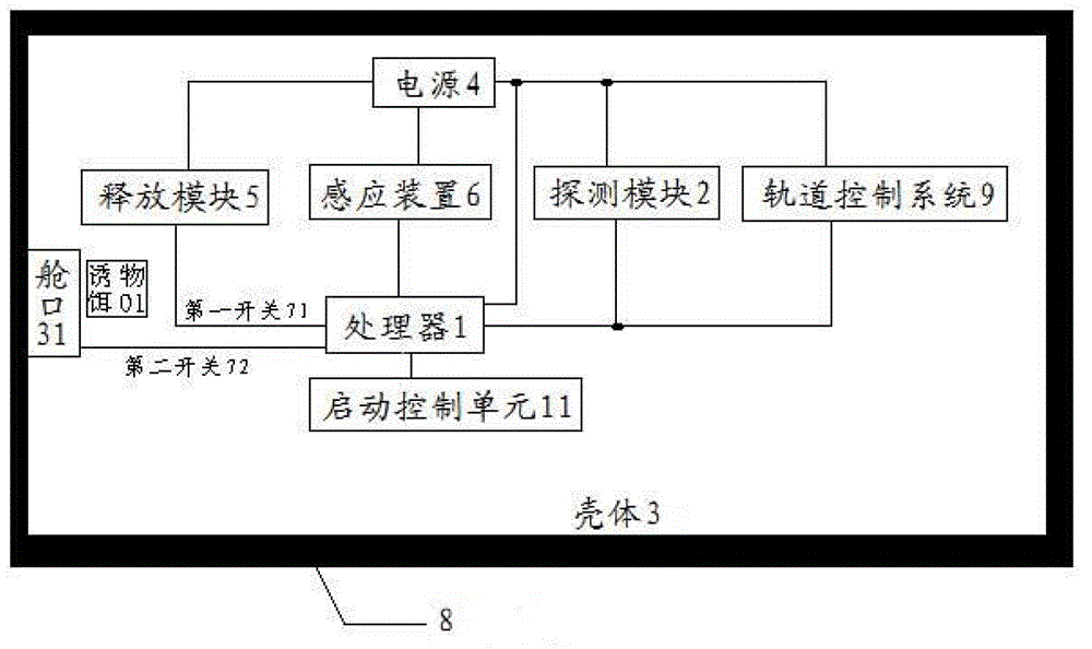
[0056] See figure 2 As shown, on the basis of Embodiment 1, the flying object further includes a startup control unit 11, which is connected to the processor 1, and controls the processor 1 to sleep when the startup condition does not come, and when the startup condition comes Control the processor 1 to start working, and the start condition includes a predetermined time or a predetermined geographic location; in this embodiment, the start control unit 11 is a timer, and when the timer reaches a predetermined time, The timer controls the processor 1 to start working; otherwise, the timer controls the processor 1 to sleep.

[0057] The anti-interception flying object capable of releasing smoke and decoys and resisting laser strikes according to the present invention further includes an activation control unit 11, which is connected to the processor 1, and controls the processor 1 to sleep when the activation condition does not arrive. And control the processor 1 to start working...


PUM


Abstract

The invention discloses an anti-interception flyer with functions of releasing smoke and a bait object and resisting laser impact. The anti-interception flyer comprises a processor, a detection module, a release module, a shell, a sensing device and a power supply, wherein the position on the shell, which is near the release module, is provided with a hatch; the hatch is connected with the processor via a second switch; when the detection module detects that a detection system traces and intercepts the flyer, a detection result is sent to the processor; the processor controls a first switch to be switched on so as to control the release module to release the smoke; the sensing device senses that the smoke exists in the shell; a sensing result is sent to the processor; according to the sensing result, the processor controls the second switch to be switched on so as to control the hatch to be opened to release module to release the smoke and the bait object; the smoke is released for confusing a detection system for tracing and intercepting; the result of the optical observation instrument of the detection system is interfered with; the detection system stops tracing and intercepting; and the flyer takes the chance to escape under the covering of the smoke.

Description

Technical field [0001] The invention relates to an anti-anti-missile technology, in particular to an anti-interception flying object capable of releasing smoke and bait objects and resisting laser strikes, belonging to the technical field of space flight. Background technique [0002] At present, space detection mainly includes radar detection, visible light detection, laser detection, infrared detection, sound wave detection and other reconnaissance detection technologies, which are used to detect and find flying objects in the air. Correspondingly, space anti-detection techniques are also tit-for-tat, using various countermeasures. The detection method realizes that the flying objects in the air are not found by various detection techniques, so that they can fly safely. [0003] With the rapid advancement of modern science, the rapid development of sound, light, electricity, and other technologies has greatly enriched the means of obtaining information, and these technologies are...

Claims


Application Information

Patent Timeline
Patent Type & Authority Patents(China)
IPC IPC(8): F42B15/00F42B15/01F42B12/36F42B12/48G02B5/124
Inventor 王海龙
Owner 启东市和洪农副产品专业合作社
Learn More