Dynamic characteristic testing system with high confining pressure and temperature control for materials

A dynamic characteristic and testing system technology, applied in the direction of analyzing materials, strength characteristics, measuring devices, etc., can solve problems such as dynamic testing of mineral or rock materials

Active Publication Date: 2013-05-01
CHONGQING UNIV
View PDF5 Cites 12 Cited by
  • Summary
  • Abstract
  • Description
  • Claims
  • Application Information

AI Technical Summary

Problems solved by technology

Existing testing technology cannot directly conduct dynamic tests on minerals or rock materials buried deep in the formation

Method used


Image

  • Dynamic characteristic testing system with high confining pressure and temperature control for materials
  • Dynamic characteristic testing system with high confining pressure and temperature control for materials
  • Dynamic characteristic testing system with high confining pressure and temperature control for materials

Examples


Embodiment 1

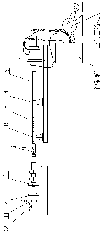
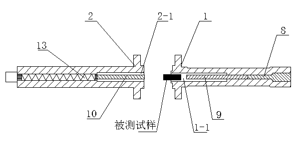
[0012] A high confining pressure temperature-controlled dynamic characteristic testing system for materials, including a sample holding device I 1 and a sample holding device II 2 that cooperate with each other, the sample holding device I 1 has an inner cylinder I 1-1, The sample holding device II 2 has an inner cylinder II 2-1. In this embodiment, the inner cylinder I 1-1 and the inner cylinder II 2-1 are cylindrical cylinders with one end open, and their axes are respectively the sample holding device I 1 and the sample holding device The axis of II 2. The axis centers of the inner cylinder I 1-1 and the inner cylinder II 2-1 coincide and the openings face each other. When the sample holding device I 1 is close to the sample holding device II 2, the inner cylinder I 1-1 and the inner cylinder II 2-1 are buckled together to form a closed container for containing the tested sample. the accommodation chamber. Preferably, the test sample used in the test is made into a cylin...

Embodiment 2

[0022] Coal rocks were tested using the device disclosed in Example 1.

[0023] In this embodiment, a coal rock with a diameter of 50mmx and a length of 50mm is used as the test sample, and the test sample is simulated to be in the state of 120 meters underground to obtain constitutive properties such as high strain rate strength, fracture characteristics and stress-strain relationship. Include the following steps:

[0024] 1) Adjust the axial feed device so that the sample holding device I 1 is separated from the sample holding device II 2. See attached figure 2 , Install the prepared test sample inside the inner cylinder I 1-1.

[0025] 2) Adjust the axial feed device so that the sample holding device I 1 and the sample holding device II 2 are combined together. That is, the inner cylinder I 1-1 and the inner cylinder II 2-1 are snapped together to form a chamber for containing the tested sample. The sample to be tested is enclosed in the accommodating cavity, and its t...


PUM


Abstract

The invention aims to provide a system which simulates the real condition of a mineral or a rock in a deep stratum and tests dynamic mechanical characteristics thereof under the condition of a laboratory on the ground, namely, a dynamic characteristic testing system with a high confining pressure and the temperature control for materials. The system comprises a sample accommodating device I and a sample accommodating device II which are mutually matched, wherein the sample accommodating device I is provided with an inner barrel I; and the sample accommodating device II is provided with an inner barrel II. When the sample accommodating device I abuts tightly against the sample accommodating device II, the inner barrel I and the inner barrel II are buckled together, so that a closed accommodating cavity for accommodating a tested sample is formed. An incidence rod is mounted in the inner barrel I, a transmission rod is mounted in the inner barrel II, and a temperature control device is mounted in the accommodating cavity formed by the inner barrel I and the inner barrel II. When the tested sample is placed in the accommodating cavity, one end of the tested sample is contacted with the head end of the incidence rod, and the other end thereof is contacted with the head end of the transmission rod.

Description

technical field [0001] The invention relates to the field of testing the dynamic mechanical properties of deep underground minerals or rocks. Background technique [0002] Mineral or rock materials buried deep in the formation are often subjected to external impacts such as gas explosions. Therefore, when designing safety, the dynamic mechanical properties of the mineral or rock materials themselves must be known in advance, such as: high strain rate strength, fracture properties and constitutive properties such as stress-strain relations. Existing testing techniques cannot directly perform dynamic tests on minerals or rock materials buried deep in the formation. Therefore, it is usually considered to simulate the state of mineral or rock material in a deep layer in the laboratory environment, and test its dynamic characteristics. Contents of the invention [0003] The purpose of the present invention is to provide a system for simulating the real state of minerals or ro...

Claims


Application Information

Patent Timeline
Patent Type & Authority Applications(China)
IPC IPC(8): G01N3/307
Inventor 王新筑郭早阳彭向和刘占芳杨春和陈斌
Owner CHONGQING UNIV
Why Eureka
Try Eureka