Knocking scan type bridge damage detecting system

一种损伤检测、敲击扫描的技术,应用在冲击测试、测量装置、弹性的测试等方向,能够解决影响桥梁正常工作、难广泛的使用、发现桥梁病害等问题,达到避免桥梁事故、检测时间短、方便快捷检测的效果

Active Publication Date: 2013-05-01
TSINGHUA UNIV +1
View PDF3 Cites 18 Cited by
  • Summary
  • Abstract
  • Description
  • Claims
  • Application Information

AI Technical Summary

Problems solved by technology

[0003] From the perspective of implementation cycle and detection accuracy, bridge inspection mainly includes two methods: regular inspection and real-time monitoring: regular inspection, such as manual inspection, bridge dynamic and static load test, etc., although this method has high accuracy, but the time interval is long, which is not conducive to Timely detection of bridge diseases requires interruption of bridge traffic, which is difficult to implement; real-time monitoring, such as some bridge health monitoring systems, although this method has good real-time performance, has low precision and high cost, so it is difficult to obtain widespread application in a short period of time. use
[0004] From the perspective of practical operation, the existing bridge damage identification technology can be divided into two methods: offline local detection and online overall monitoring. , electromagnetic eddy current, X-ray, etc., to carefully detect the damage in the structure. This method has high detection accuracy, but it often needs to interrupt the traffic and affect the normal operation of the bridge, and it is necessary to know the approximate location of the damage in advance. There are detection dead ends. Low efficiency; on-line overall monitoring is to preset sensors in the bridge structure to obtain structural response signals in real time to infer the damage in it. Although this method does not need to interrupt bridge traffic, the detection accuracy is low, and there are still sensors installation, transmission and storage of massive signals, noise immunity and durability of sensors, etc.

Method used


Image

  • Knocking scan type bridge damage detecting system
  • Knocking scan type bridge damage detecting system
  • Knocking scan type bridge damage detecting system

Examples


Embodiment Construction

[0042] In order to make the objectives, technical solutions and advantages of the embodiments of the present invention clearer, the specific embodiments will be described in detail below with reference to the accompanying drawings.

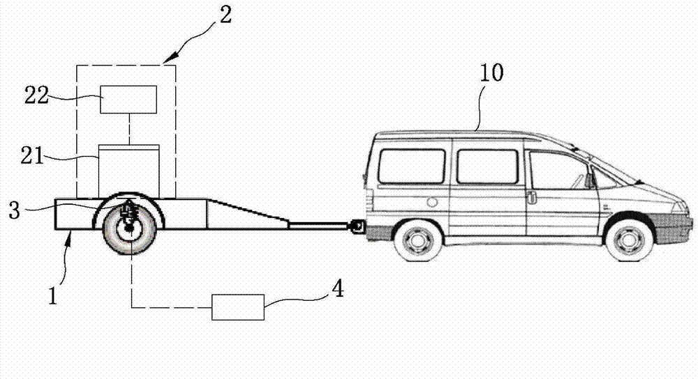
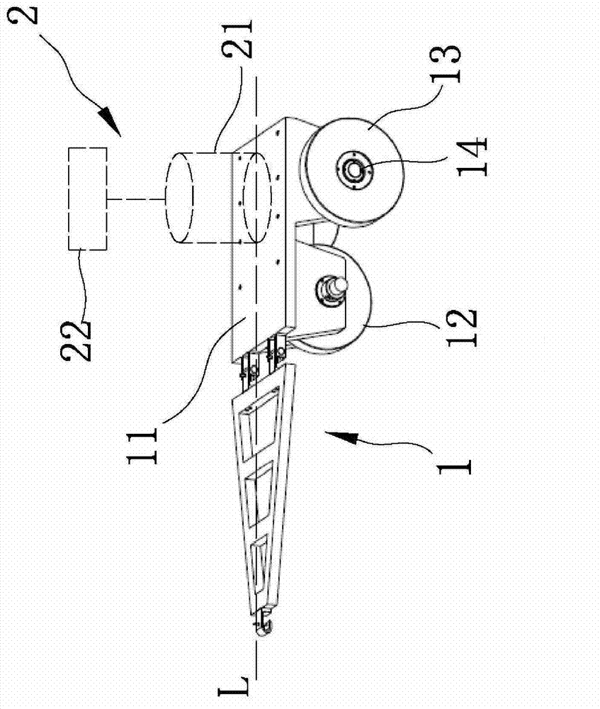
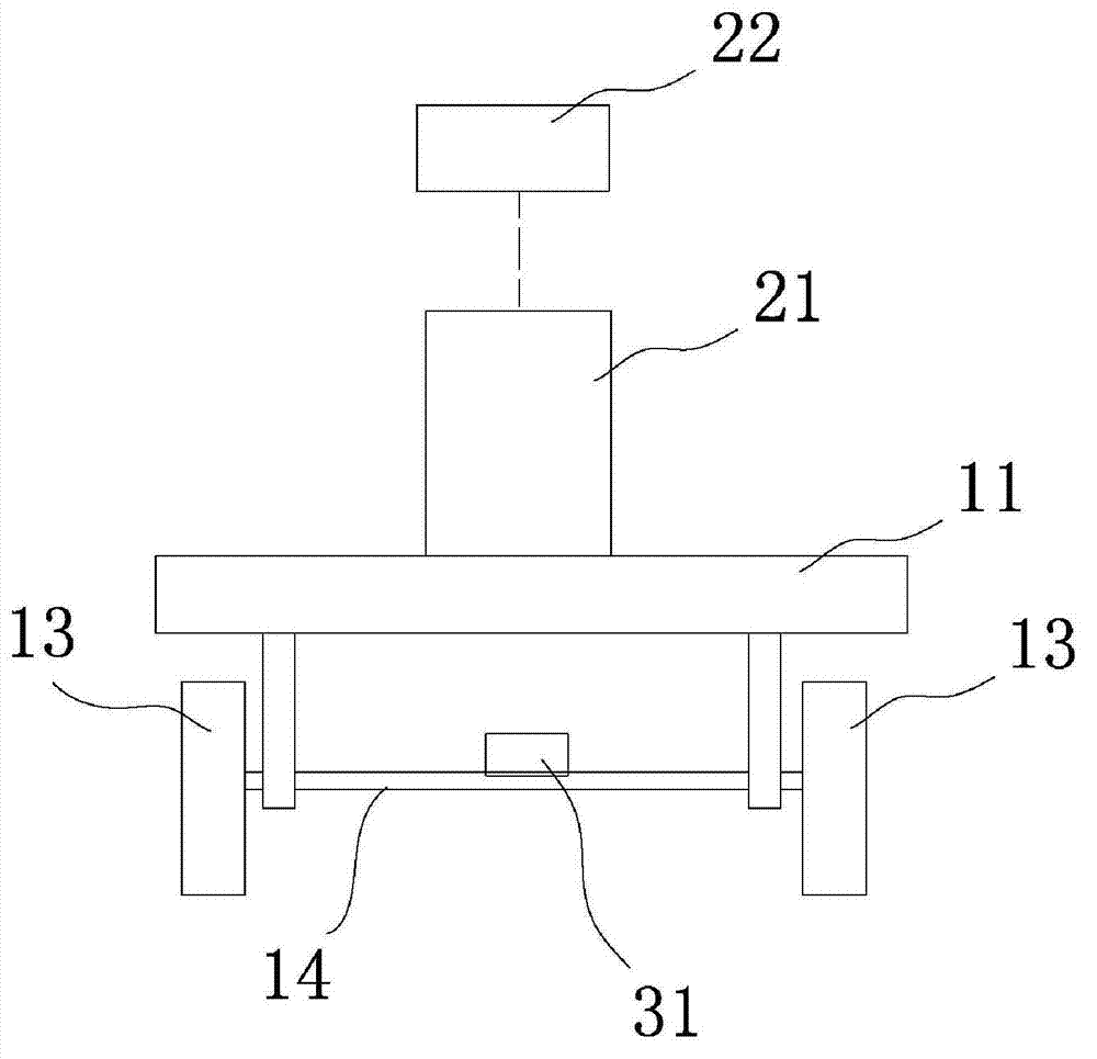
[0043] Please refer to figure 1 , is a schematic diagram of the composition of the knock-scanning bridge damage detection system of the present invention. As shown in the figure, the knock-scanning bridge damage detection system of the present invention mainly includes: a mobile trolley 1, which can move on the bridge to be tested; knocking subsystem 2. It is located on the mobile trolley 1 and can move with the mobile trolley 1. The knocking subsystem 2 is mainly used to apply knocking load to the bridge to be tested, and it can move the moving trolley 1 to the bridge to be tested while moving. The bridge applies a knocking load; the signal acquisition subsystem 3 is located in the mobile trolley 1, and is used to collect the response signal of t...


PUM


Abstract

The invention discloses a knocking scan type bridge damage detecting system which comprises a traveling car, a knocking subsystem, a signal acquisition subsystem and a signal processing device. The traveling car can move on a to-be-detected bridge; the knocking subsystem is arranged on the traveling car, and is used for applying a knocking load to the to-be-detected bridge; the signal acquisition subsystem is arranged on the traveling car and is used for collecting a response signal transferred from the to-be-detected bridge to the traveling car; and the signal processing devise is connected with the signal acquisition subsystem, and is used for receiving and processing the signal collected by the signal acquisition subsystem, and outputting the bridge damage information processed result. The knocking scan type bridge damage detecting system provided by the invention can detect bridge damage information in a simple, convenient, efficient and high-accuracy manner.

Description

technical field [0001] The invention relates to a bridge damage detection system, in particular to a percussion scanning bridge damage detection system. Background technique [0002] With the advancement of science and technology and the improvement of transportation demand, the number of various highway and rail transit bridges has increased rapidly. During the use of these bridges, they are constantly eroded by external environments such as temperature changes, strong winds, and rainfall, and at the same time by vehicles. The long-term repeated action of load and vehicle impact, and some bridges will also be damaged by natural disasters such as floods and earthquakes. External damage has caused many bridges to become dangerous bridges in a certain sense. There have been a large number of collapse examples of bridges at home and abroad, which have seriously threatened people's life and property safety. Therefore, it is very important to detect bridges in real time and effec...

Claims


Application Information

Patent Timeline
Patent Type & Authority Applications(China)
IPC IPC(8): G01N29/04
CPCG01N29/04G01M5/0066G01N29/265G01N29/045G01M5/0033G01N2291/0232G01M5/0075G01M5/0008G01M7/08G01N29/46
Inventor 陆秋海向志海王珑祺张程浩沈兆普周马生杨小刚
Owner TSINGHUA UNIV
Why Eureka
Try Eureka