Building concealed circuit threader

A technology for wire threaders and buildings, applied to electrical components, cable laying equipment, etc., can solve the problems of high labor intensity, low work efficiency, waste of working hours, etc., and achieve the effects of low labor intensity, high work efficiency and cost reduction

Active Publication Date: 2013-05-01
吴朕国
View PDF3 Cites 22 Cited by
  • Summary
  • Abstract
  • Description
  • Claims
  • Application Information

AI Technical Summary

Problems solved by technology

This method requires at least two people to operate, one person feeds the wire, and one person connects the wires. The labor intensity is very high, and communication is inconvenient. It is often necessary to run up and down, wasting a lot of man-hours, and sometimes dama

Method used


Image

  • Building concealed circuit threader
  • Building concealed circuit threader
  • Building concealed circuit threader

Examples


Embodiment Construction

[0031] The general idea of ​​the present invention is to drive the traction wire forward and backward through the remote control motor to carry out the traction and installation operation of the wire in the wall. An embodiment is described below in conjunction with the accompanying drawings:

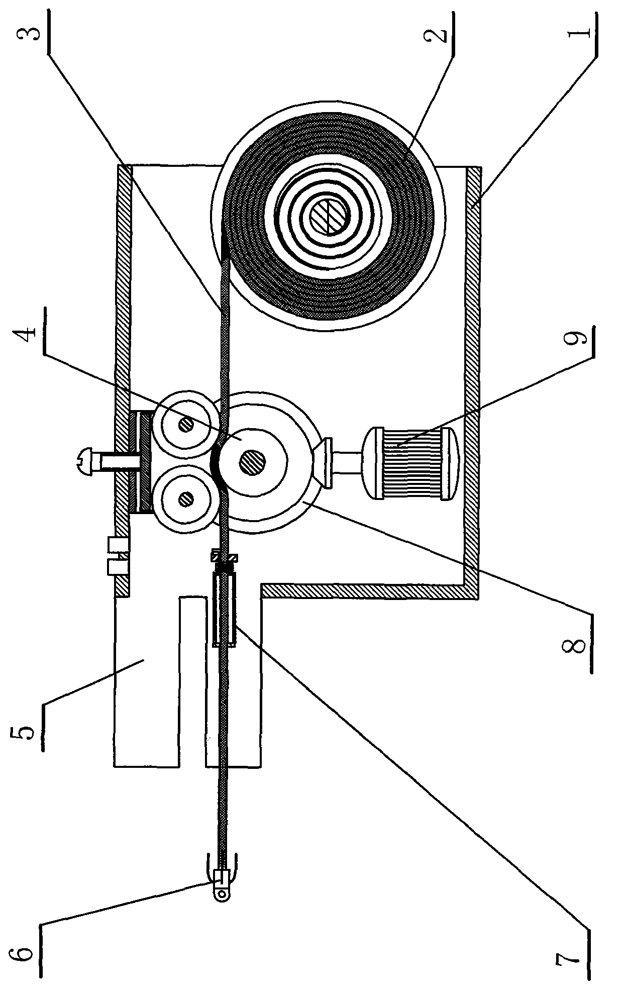
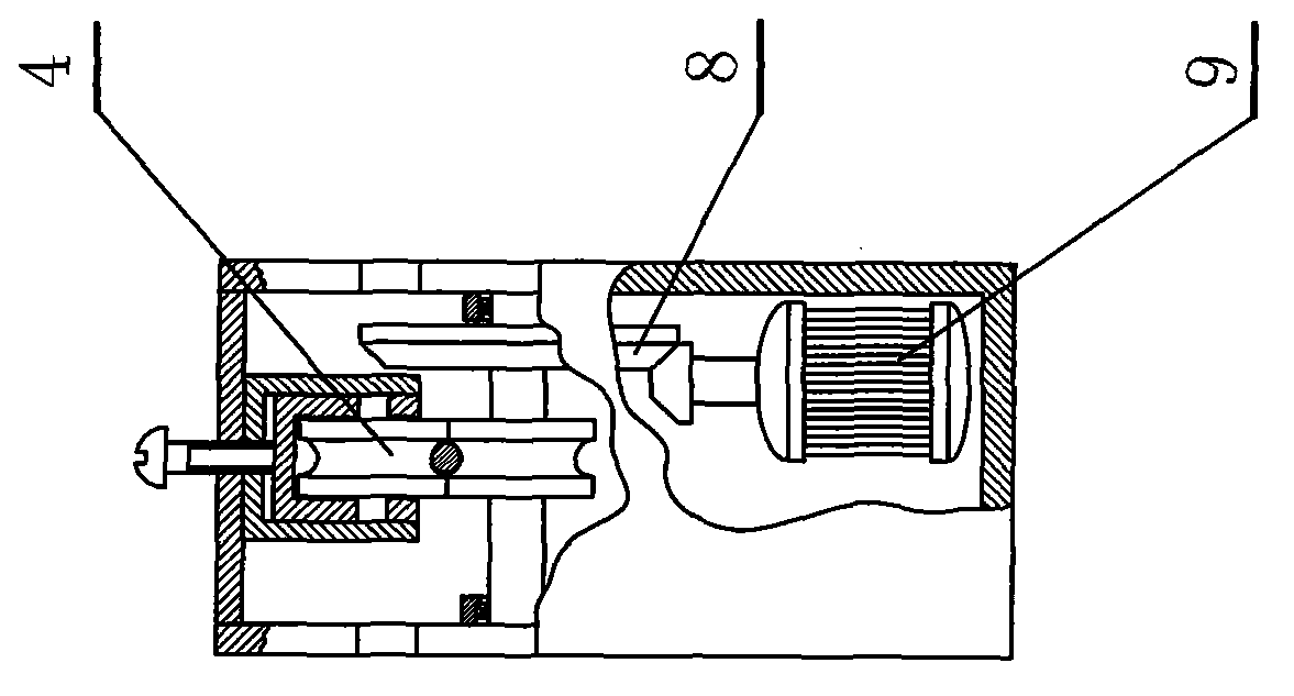
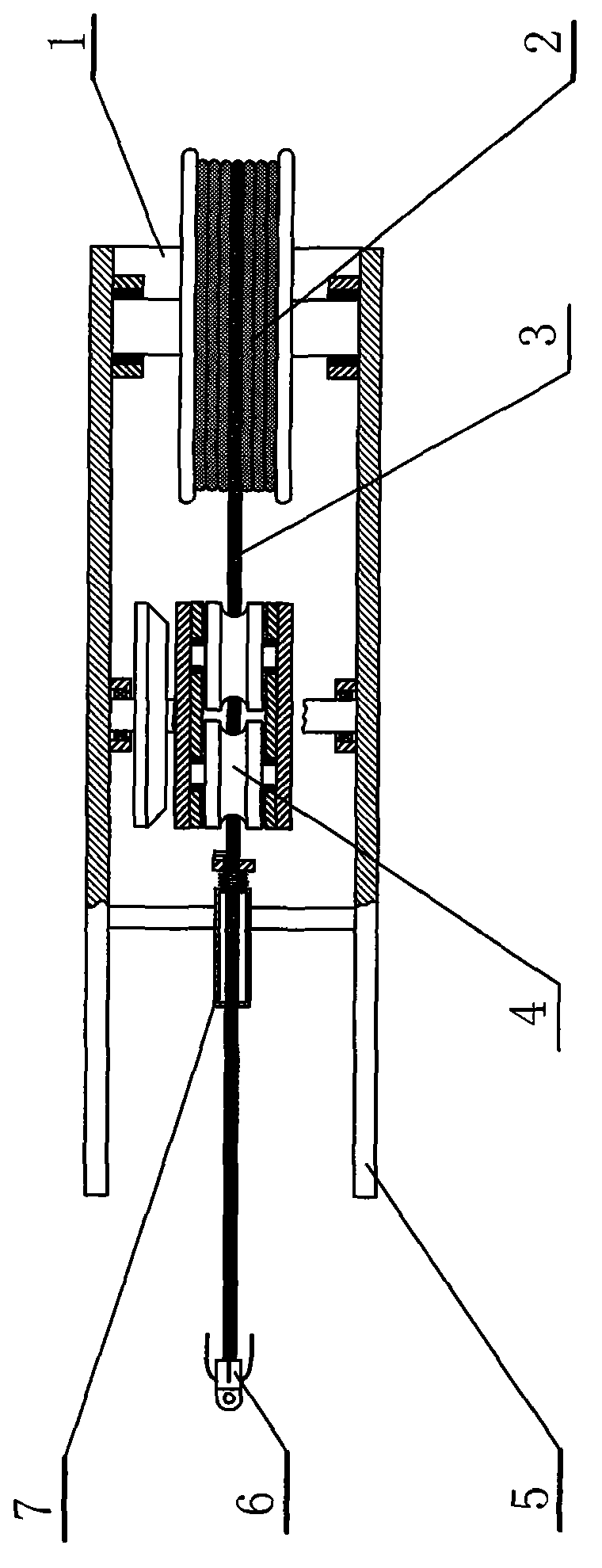
[0032] figure 1 , 2 , 3 introduce a threader, a reel 2 and a clamping mechanism 4 are arranged in a casing 1, and the clamping mechanism clamps the traction wire 3 under the drive of the motor 9 to realize the forward or reverse action.

[0033] combine Figure 4 , 5 , 6, it can be seen that the shell 1 is in the shape of a flat cube, and the front part is provided with four inserts 5, which can be inserted into the wire box on one side of the conduit. The upper surface of the housing 1 is provided with an indicator light 10, and one side is provided with a forward rotation button 11 and a reverse rotation button 12.

[0034] combine Figure 7 , 8 It can be seen that the reel 2 ha...


PUM


Abstract

The invention relates to an electromechanical apparatus, namely a building concealed circuit threader comprising a pull wire (3) which can be inserted into wire conduit (31) openings (32) and can pass through in the wire conduit (31). The building concealed circuit threader is characterized in that the threader is provided with a box-shaped shell (1), the front end of the shell (1) is provided with plugboards (5) matched with the wire conduit openings, the shell (1) is internally provided with a reel (2) for reeling the pull wire (3), a clamping device (4) for the pull wire (3) is arranged between the plugboards (5) and the reel (2), and the clamping device (4) is connected with an electric motor (9) by a drive disk assembly. The building concealed circuit threader has the beneficial effects that the plugboards are inserted into the openings at one part, and one person controls the threader remotely to perform threading operation, thus the labour intensity is low, the working performance is high, and the theader is hopeful to be the necessary apparatus for the building concealed circuit installation.

Description

technical field [0001] The invention relates to an electromechanical apparatus, that is, a wire threader for concealed circuits in buildings. Background technique [0002] Most of the circuit conductors equipped in buildings are hidden lines buried in the wall conduits. Due to the long lines, the installation is very difficult. The existing installation method is manual operation, inserting a pulling wire from one opening of the conduit, passing along the conduit to another opening to hook the wire, and then pulling the pulling wire back to pull the wire to an opening. This method requires at least two people to operate, one to send the wire and the other to connect the wire, which is labor-intensive and inconvenient to communicate. The traction wire used is replaced by steel wire, which is not only inconvenient for wiring, but also often bends and gets stuck in the process of pipe threading, which is not smooth and the work efficiency is very low. SUMMARY OF THE INVENTIO...

Claims


Application Information

Patent Timeline
IPC IPC(8): H02G1/08H02G3/38
Inventor 吴朕国
Owner 吴朕国
Why Eureka
Try Eureka