Current control method during necking detection of molten electrode arc welding

A melting electrode, arc welding technology, applied in arc welding equipment, welding equipment, manufacturing tools, etc., can solve the problems of instability, unable to suppress sputtering, unable to suppress welding state, etc. stable effect

Active Publication Date: 2016-03-16
DAIHEN CORP
View PDF10 Cites 0 Cited by
  • Summary
  • Abstract
  • Description
  • Claims
  • Application Information

AI Technical Summary

Problems solved by technology

If the delay period Td is not set in this way, the occurrence of sputtering cannot be suppressed, and the welding state cannot be suppressed from becoming unstable.

Method used


Image

  • Current control method during necking detection of molten electrode arc welding
  • Current control method during necking detection of molten electrode arc welding
  • Current control method during necking detection of molten electrode arc welding

Examples


no. 1 approach

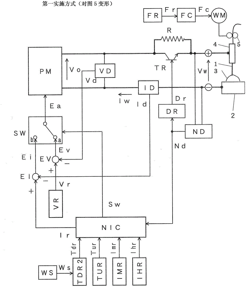
[0099] figure 1 It is a block diagram of a welding power source for carrying out the current control method at the time of constriction detection in metal arc welding according to the first embodiment of the present invention. The figure is in the above Figure 5 Increase the welding speed setting circuit WS, will Figure 5 The delay period setting circuit TDR is replaced by the second delay period setting circuit TDR2. In this figure, for Figure 5 For the same boxes, the same symbols are attached and their descriptions are omitted. Hereinafter, the different blocks will be described with reference to this figure.

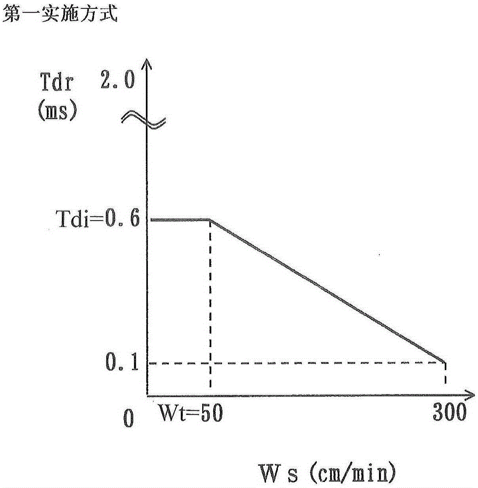
[0100]The welding speed setting circuit WS outputs a predetermined welding speed setting signal Ws. In the welding apparatus using a robot, since the welding speed is set in a robot control device (not shown), information related to the welding speed is sent from the robot control device to the welding speed setting circuit WS. Then, this welding speed sett...


PUM

PropertyMeasurementUnit
diameteraaaaaaaaaa

Abstract

The invention provides a current control method during necking detection of fusion electrode electric arc welding. Detection is performed on a precursory phenomenon which generates arcs again from a short circuit state, that is molten drop necking. If the necking is detected, then the welding current electrified in short circuit loads is enabled to be reduced, and then from a moment that the arc is generated again to a moment of delay period (Tdr), the welding current is increased and is electrified in the arc loads; and when the welding speed (Ws) is smaller than a reference speed (Wt), the delay period (Tdr) is set to be a fixed vale (Tdi) no matter what the value of the welding speed (Ws) is, and when the welding speed (Ws) is larger than the reference speed (Wt), the delay period (Tdr) changes on the basis of the welding speed (Ws). As a result, since the delay period (Tdr) is optimized on the basis of the welding speed (Ws), good welding quality can be obtained even if the welding speed (Ws) changes. And during the arc welding that the detection on molten drop necking is used for controlling the welding current, good welding quality can be obtained even if the welding speed changes.

Description

technical field [0001] The present invention relates to a current control method for detecting constriction of molten droplet during short circuit and reducing welding current to reduce sputtering just before arc re-occurrence. Background technique [0002] Figure 4 It is a current-voltage waveform diagram and a droplet transfer diagram of molten electrode arc welding in which the short-circuit period Ts and the arc period Ta are repeated. The figure (A) shows the change with time of the welding current Iw applied to the molten electrode (hereinafter referred to as welding wire 1), and the figure (B) shows the change with time of the welding voltage Vw applied between the welding wire 1 and the base metal 2. Changes of the figure (C) to (E) show the state of the droplet 1a transition. Hereinafter, description will be made with reference to this figure. [0003] During the short-circuit period Ts from time t1 to t3, the droplet 1a at the tip of the welding wire 1 is in a s...

Claims


Application Information

Patent Timeline
Patent Type & Authority Patents(China)
IPC IPC(8): B23K9/095B23K9/173
Inventor 井手章博惠良哲生
Owner DAIHEN CORP
Why Eureka
Try Eureka