

Arc welding method and arc welding device
An arc welding method and arc welding technology, applied in arc welding equipment, welding equipment, manufacturing tools and other directions, can solve the problems of embrittlement of the welding part, increase of welding time, deformation of the base metal, etc., to suppress the generation of sputtering, Stable buried space and stable welding effect
- Summary
- Abstract
- Description
- Claims
- Application Information
AI Technical Summary
Problems solved by technology
Method used
Image

Examples
Embodiment approach 1
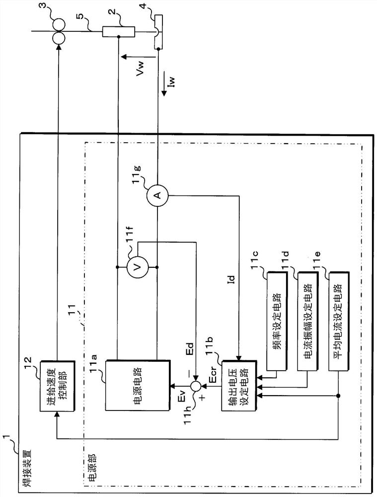
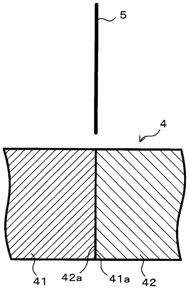
[0046] figure 1 It is a schematic diagram which shows one structure of the arc welding apparatus concerning this Embodiment 1. The arc welding device according to Embodiment 1 is a consumable electrode type shielding gas arc welding machine capable of butt welding a base material 4 having a plate thickness of 9 to 30 mm in a single pass. In particular, the arc welding apparatus according to the first embodiment enters into the buried space 6a by controlling the welding current Iw (refer to Figure 4 ), the position of the front end portion 5a of the welding wire 5 can be stably maintained by performing the droplet transfer several times during the transition from the position of the front end portion 5a of the welding wire 5 to a high state, thereby stably maintaining the buried space 6a. The generation of sputtering can be suppressed.
[0047] The arc welding device according to Embodiment 1 includes a welding power source 1 , a welding torch 2 , and a wire feeder 3 .
[0...
Embodiment approach 2
[0089] The arc welding method and arc welding apparatus according to the second embodiment are different from those of the first embodiment in the method of controlling the welding current Iw, and therefore the relevant differences will be mainly described below. The other configurations and functions and effects are the same as those in Embodiment 1, so corresponding parts are assigned the same reference numerals and detailed descriptions thereof are omitted.
[0090] Figure 7 It is a graph which shows the fluctuation|variation of the welding current Iw concerning this Embodiment 2. The horizontal axis of the graph represents time, and the vertical axis represents welding current Iw. In addition, the state of the droplet transfer accompanying the change of the welding current Iw is schematically shown in the upper part of the graph.
[0091] In Embodiment 2, the power supply unit 11 controls so that the high-current period is longer than the low-current period, and the wel...
Embodiment approach 3
[0094] The arc welding method and arc welding apparatus according to Embodiment 3 differ from Embodiment 1 in the method of controlling the welding current Iw, and the relevant differences will be mainly described below. The other configurations and functions and effects are the same as those in Embodiment 1, so corresponding parts are assigned the same reference numerals and detailed descriptions thereof are omitted.
[0095] Figure 8 It is a graph which shows the fluctuation|variation of the welding current Iw concerning this Embodiment 3. The horizontal axis of the graph represents time, and the vertical axis represents welding current Iw. In addition, the state of the droplet transfer accompanying the change of the welding current Iw is schematically shown in the upper part of the graph.
[0096] In Embodiment 3, the power supply unit 11 controls the output of the welding current Iw so that the welding current Iw increases stepwise during the high current period. For e...
PUM
| Property | Measurement | Unit |
|---|---|---|
| diameter | aaaaa | aaaaa |
| thickness | aaaaa | aaaaa |
Abstract
Description
Claims
Application Information