Arc welding device and arc welding system

An arc welding and arc technology, applied in the field of arc welding devices and arc welding systems, can solve the problems of lack of heat input, sputtering, etc.

Active Publication Date: 2015-05-20
YASKAWA DENKI KK
View PDF6 Cites 0 Cited by
  • Summary
  • Abstract
  • Description
  • Claims
  • Application Information

AI Technical Summary

Problems solved by technology

[0005] The increase rate of the short-circuit current is set to a large value in advance considering the lack of heat input and the response when the welding becomes unstable, and spattering is highly likely

Method used


Image

  • Arc welding device and arc welding system
  • Arc welding device and arc welding system
  • Arc welding device and arc welding system

Examples


Embodiment Construction

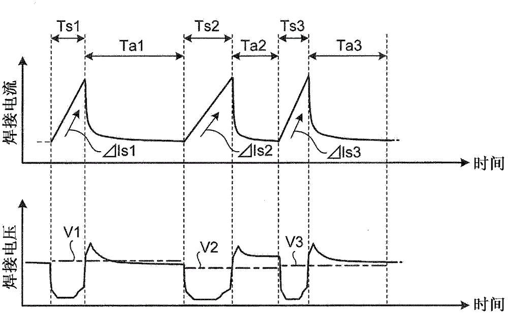
[0014] An arc welding apparatus according to one embodiment performs welding while repeatedly generating a short-circuit state and an arc state between a consumable electrode and a welding member. The arc welding device includes a detection unit and an adjustment unit. The detection unit detects at least one of the duration of the current short circuit and the duration of the current arc. The adjustment unit adjusts the increase rate of the short-circuit current in the next short-circuit generation period according to at least one of the short-circuit generation duration and the arc generation duration detected by the detection unit.

[0015] Embodiments of the arc welding apparatus and the arc welding system disclosed in the present application will be described below based on the drawings.

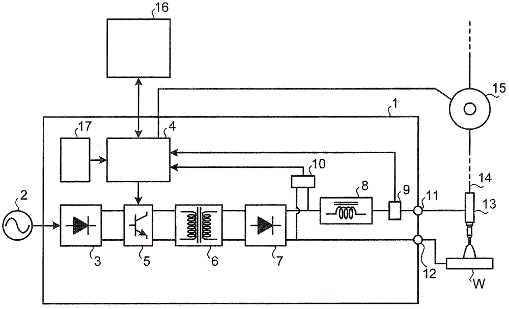
[0016] figure 1 is a configuration diagram of an arc welding apparatus according to one embodiment. The arc welding power source 1 is powered by an AC (alternating current) commercia...


PUM


Abstract

An arc welding device according to an embodiment carries out welding while repeatedly generating a short circuit state and an arc state between a consumable electrode (14) and a welding member (W). The arc welding device includes a detection unit (4) and an adjustment unit (4). The detection unit (4) detects at least one of a length of a short circuit generation period of this time and a length of an arc generation period of this time. The adjustment unit (4) adjusts an increase rate of a short circuit current in a short circuit generation period of next time according to at least one of the length of the short circuit generation period and the length of the arc generation period detected by the detection unit (4).

Description

technical field [0001] Embodiments discussed herein relate to arc welding apparatus and arc welding systems. Background technique [0002] In gas shielded arc welding using a consumable electrode, many welding methods for suppressing sputtering and performing stable welding have been proposed in the prior art. [0003] In the method for controlling an arc welding device, an arc generation duration of a certain time is detected, and during a next arc welding generation period, an output voltage of a welding power source is decreased in proportion to the detected arc generation duration, and at this During the next arc generation period, the welding current is increased in a manner inversely proportional to the arc generation time of the certain time, the purpose of which is to enhance the response speed and quickly return to a stable welding state. The technique described in Japanese Patent Publication No. 4028075 relates to such prior art. [0004] However, in the conventi...

Claims


Application Information

Patent Timeline
Patent Type & Authority Patents(China)
IPC IPC(8): B23K9/173B23K9/095
CPCB23K9/1006B23K9/092B23K9/0953B23K9/173
Inventor 村上真史平山卓秀
Owner YASKAWA DENKI KK
Why Eureka
Try Eureka