Steel bar positioning mechanism for mesh welding machine

Pending Publication Date: 2022-04-29
孙进松
View PDF1 Cites 0 Cited by
  • Summary
  • Abstract
  • Description
  • Claims
  • Application Information

AI Technical Summary

Problems solved by technology

[0002] The welding mesh machine is a mesh equipment that welds the horizontal steel bar and the longitudinal steel bar into the required specifications by welding. The longitudinal steel bar is mainly used as a stressed steel bar. The mesh machine is welded with the set horizontal steel bars, but the longitudinal steel bars will vibrate during the conveying process, which will prevent the horizontal steel bars from being unstable and cannot ensure the accuracy of welding, so the longitudinal steel bars need to be positioned
[0003] After retrieval, Chinese patent 201922459973.2 discloses a steel bar positioning mechanism for a welding mesh machine, which has the advantages of being able to quickly install and position longitudinal bars, and can adjust the distance between two adjacent sets of longitudinal bars as required, but the patent It is impossible to adjust the spacing between all longitudinal steel bars, and it cannot achieve the effect of synchronous adjustment, so it has no practicality

Method used


Image

  • Steel bar positioning mechanism for mesh welding machine
  • Steel bar positioning mechanism for mesh welding machine
  • Steel bar positioning mechanism for mesh welding machine

Examples


Embodiment Construction

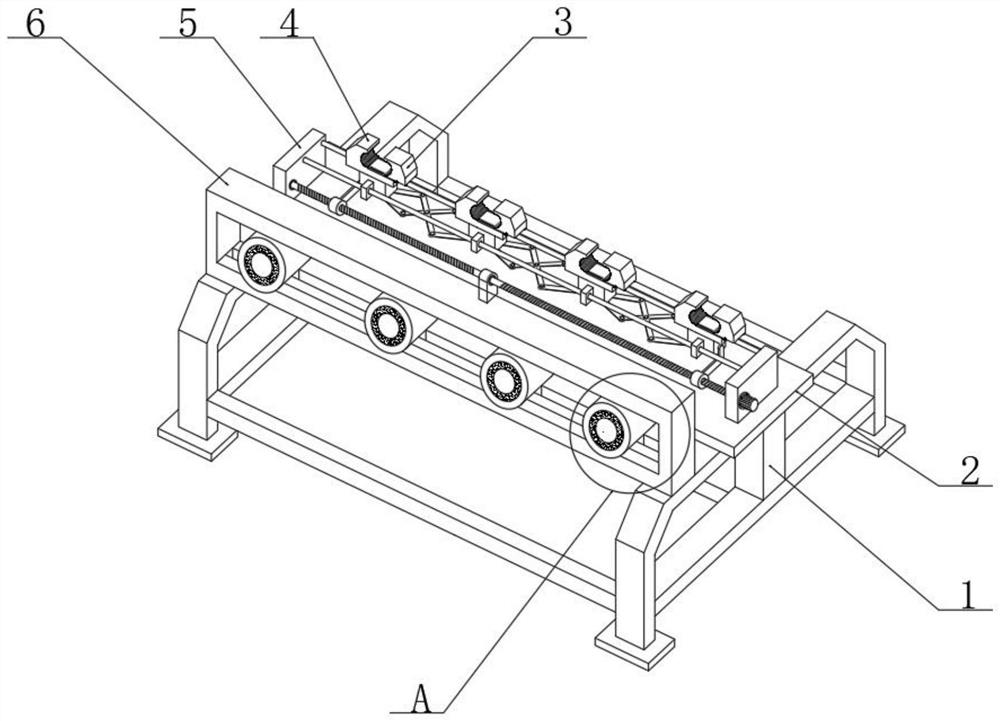
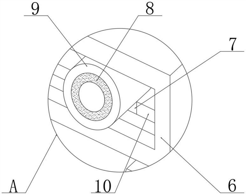
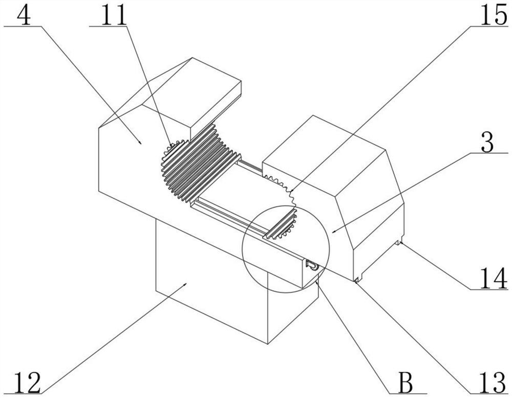
[0022] see Figure 1~5 , in an embodiment of the present invention, a steel bar positioning mechanism for a welding mesh machine includes an underframe 1, a bearing plate 2 is fixed above the underframe 1, and several steel bars with different diameters are arranged above the bearing plate 2. The variable diameter jaw includes a positioning clamp 4, the bottom of the positioning clamp 4 is fixed with a base 12, and a movable clamp 3 slides above one side of the positioning clamp 4, and the positioning clamp 4 and the movable clamp The opposite sides of 3 are respectively provided with a first half-arc groove 11 and a second half-arc groove 15, and the inner sides of the first half-arc groove 11 and the second half-arc groove 15 are provided with anti-slip teeth, which can play an anti-slip effect;

[0023] The opening and closing between the positioning clamp block 4 and the movable clamp block 3 is realized by a driving mechanism. The driving mechanism includes two second sli...


PUM


Abstract

The invention relates to the technical field of mesh welding machines, in particular to a steel bar positioning mechanism for a mesh welding machine, a bearing plate is fixed above a bottom frame, and a pretreatment mechanism for removing rust of steel bars is arranged at the position, located on the front side of the bearing plate, above the bottom frame; a plurality of variable-diameter clamping nozzles used for reinforcing steel bars with different diameters are arranged above the bearing plate, and the variable-diameter clamping nozzles are connected through a synchronous distance adjusting mechanism and used for adjusting the distance between every two adjacent variable-diameter clamping nozzles, so that the distance between the reinforcing steel bars in the radial direction is adjusted. The device is simple in structure and easy and convenient to operate, reinforcing steel bars are attached to the first semi-arc groove in the conveying process, longitudinal reinforcing steel bars can be limited in the conveying process, the second semi-arc groove gets close to the first semi-arc groove to clamp the longitudinal reinforcing steel bars during welding, the phenomenon of unstable welding caused by shaking of equipment is avoided, and the welding quality is improved. And the welding precision is effectively guaranteed, and meanwhile the requirement for steel wires with different diameters can be met.

Description

technical field [0001] The invention relates to the technical field of wire mesh welding machines, in particular to a steel bar positioning mechanism for wire mesh welding machines. Background technique [0002] The welding mesh machine is a mesh equipment that welds the horizontal steel bar and the longitudinal steel bar into the required specifications by welding. The longitudinal steel bar is mainly used as a stressed steel bar. The mesh machine is welded with the set horizontal steel bars, but the longitudinal steel bars will vibrate during the conveying process, which will prevent the horizontal steel bars from being unstable, and the accuracy of welding cannot be guaranteed, so the longitudinal steel bars need to be positioned. [0003] After retrieval, Chinese patent 201922459973.2 discloses a steel bar positioning mechanism for a welding mesh machine, which has the advantages of being able to quickly install and position longitudinal bars, and can adjust the distance...

Claims


Application Information

Patent Timeline
Patent Type & Authority Applications(China)
IPC IPC(8): B23K37/04B23K37/047B24B27/033
CPCB23K37/0443B23K37/047B24B27/033
Inventor 孙进松
Owner 孙进松
Why Eureka
Try Eureka