Welding method and system for traction frame workpiece
What is AI technical title?
AI technical title is built by PatSnap AI team. It summarizes the technical point description of the patent document.
A welding method and welding system technology, applied in welding equipment, manufacturing computing systems, metal processing, etc., can solve problems such as unstable welding of welds and welding quality of complex workpieces.
Active Publication Date: 2020-11-06
烟台万兴汽车配件有限公司
View PDF7 Cites 0 Cited by
Summary
Abstract
Description
Claims
Application Information
AI Technical Summary
This helps you quickly interpret patents by identifying the three key elements:
Problems solved by technology
Method used
Benefits of technology
Problems solved by technology
[0005] In view of the deficiencies in the prior art, one of the purposes of the present invention is to provide a drawer workpiece that can avoid the problem of unstable welding of the manipulator arm to the corner weld through effective welding logic arrangement, and improve the welding quality of complex workpieces. Welding method
Method used
Image
Click on the blue label to locate the original text in one second.
Reading with bidirectional positioning of images and text.
Examples
Embodiment 1
[0072] The invention discloses a welding method for a traction frame workpiece, which is characterized in that it comprises the following steps:
[0073] Invoke the workpiece parameter information, and use software such as SolidWorks or CAD with 3D drawing function to draw the 3D drawing of the workpiece.
[0074] Generate split data in response to the workpiece split information input from the outside.
[0075] The workpiece splitting information input by the operator includes which components the workpiece is composed of and the weld positions and connection relationships among the components.
[0076] Call the split data to split the 3D image of the workpiece.
[0077] By splitting the three-dimensional image of the workpiece, the complete workpiece can be split into multiple parts according to the actual situation and the position of the weld can be reflected.
[0078] Call the 3D view of the workpiece, draw the weld at the split position of the 3D view of the workpiece,...
Embodiment 2
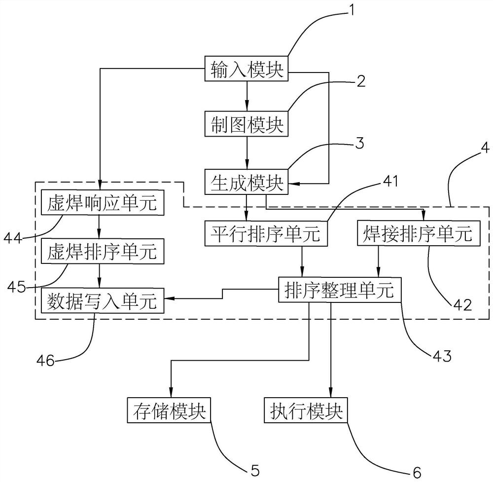
[0105] 11. On the basis of Example 1, refer to figure 1 , the invention discloses a system for welding a workpiece using a traction frame, comprising:
[0106] The input module 1 includes input devices such as a keyboard, and responds to externally input workpiece parameter information, workpiece split information, end point length and solder joint data.
[0107] Drawing module 2, call the workpiece parameter information and workpiece disassembly information, start SolidWorks or CAD and other software with 3D drawing function to draw the 3D diagram of the workpiece and split the 3D diagram of the workpiece into the state of component assembly according to the workpiece disassembly information.
[0108] The generation module 3 calls the workpiece split information and the three-dimensional map of the workpiece, and draws the weld seam according to the weld seam content of the workpiece split information on the three-dimensional map of the workpiece to generate weld seam data; ...
PUM
Abstract
The invention relates to a welding method and system for a traction frame workpiece. The welding method comprises the following steps: calling workpiece parameter information, and drawing a three-dimensional image of the workpiece; generating split data in response to workpiece split information input from the outside; calling the split data to split the three-dimensional image of the workpiece; calling the three-dimensional image of the workpiece, drawing weld joints in the split position of the three-dimensional image of the workpiece to generate weld joint data; calling the three-dimensional image of the workpiece in response to a given endpoint length, and marking spot weld sections at both ends of the weld joints; traversing the weld joint data to judge whether there are two or more weld joints mutually communicate, and if yes, marking the positions where the weld joints communicate as reinforcement sites; setting a welding priority and generating priority data; and calling the welding priority data and controlling a welding gun to perform welding according to the welding priority. The welding method has the effect of avoiding the problem of instability of fillet welding jointwelding in the mechanical arm welding through the effective welding logic arrangement, and improving the welding quality of complex workpieces and special welding joints.
Description
technical field [0001] The invention relates to the technical field of special seam welding, in particular to a welding method and system for traction frame workpieces. Background technique [0002] At present, agricultural and industrial vehicles such as tractors need to connect the front of the vehicle and the loading platform. Usually, the connection position is connected by a traction frame, and the connection frame usually needs to use a variety of mutual cooperation in order to achieve stable traction effect and efficient disassembly effect. Because the workpieces of the traction frame are dense and the functionality of the workpiece is strong, the welding structure of the workpiece for the traction frame is usually complicated, and each workpiece requires multiple weldings at different angles to complete the production operation. [0003] The existing technical solution can refer to the Chinese invention patent whose application publication number is CN109604769A, whi...
Claims
Application Information
Patent Timeline
Application Date:The date an application was filed.
Publication Date:The date a patent or application was officially published.
First Publication Date:The earliest publication date of a patent with the same application number.
Issue Date:Publication date of the patent grant document.
PCT Entry Date:The Entry date of PCT National Phase.
Estimated Expiry Date:The statutory expiry date of a patent right according to the Patent Law, and it is the longest term of protection that the patent right can achieve without the termination of the patent right due to other reasons(Term extension factor has been taken into account ).
Invalid Date:Actual expiry date is based on effective date or publication date of legal transaction data of invalid patent.

