Opposite jacking type winding spot welding device

A spot welding device and winding technology, which is applied in auxiliary devices, welding equipment, auxiliary welding equipment, etc., can solve the problem of small skeleton size

Pending Publication Date: 2021-08-24
珠海科丰电子有限公司
View PDF0 Cites 0 Cited by
  • Summary
  • Abstract
  • Description
  • Claims
  • Application Information

AI Technical Summary

Problems solved by technology

The rotating spindle fixes the skeleton in different ways, including penetrating through holes on the skeleton or grasping the skeleton through multiple claws, but the skeleton is too small to fix the skeleton more firmly before winding

Method used


Image

  • Opposite jacking type winding spot welding device
  • Opposite jacking type winding spot welding device
  • Opposite jacking type winding spot welding device

Examples


Embodiment Construction

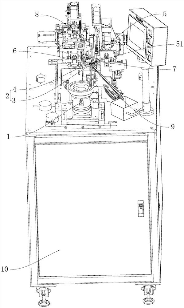
[0043] The top-to-top winding spot welding device of the present invention is used to process the skeleton winding spot welding into an inductance coil, and the inductance coil can be used in a transformer. The top-to-top winding spot welding device can process skeletons of different sizes, and is especially suitable for the winding spot welding process of small skeletons. The skeleton is clamped relatively by the moving shaft and the fixed shaft to improve the stability of the skeleton. .

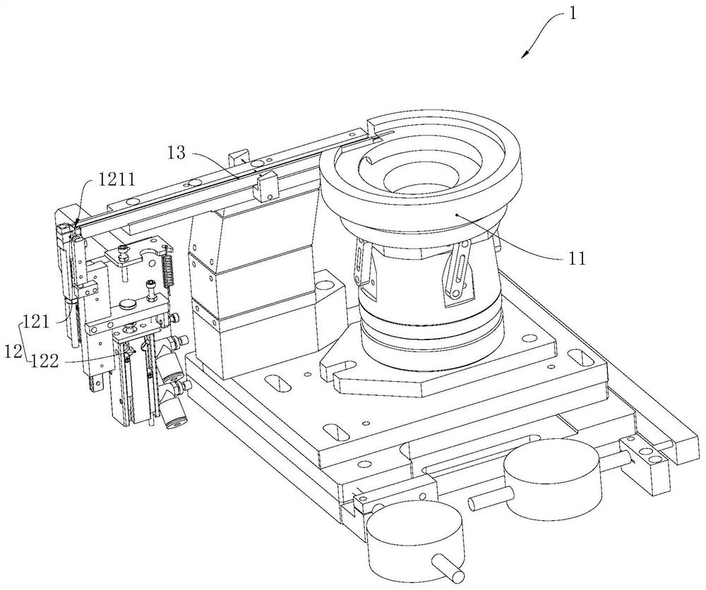
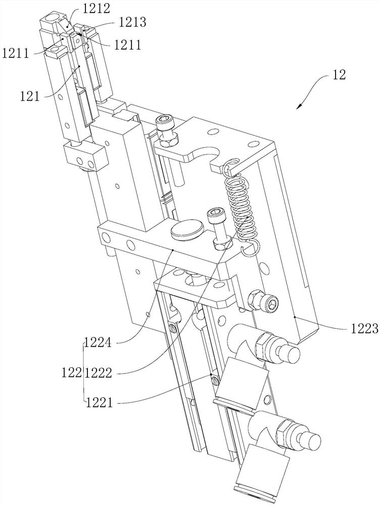
[0044] see figure 1 , the top-to-top winding spot welding device includes a mounting table 10, a feeding assembly 1, a spindle assembly 2, a winding assembly 5, a spot welding assembly 6, a clamping assembly 7, a pressing assembly 8, and a blanking assembly 9. Component 1, spindle component 2, winding component 5, spot welding component 6, clamping component 7, crimping component 8 and unloading component 9 are set on the installation platform 10 respectively, and feeding component 1 is u...


PUM


Abstract

The invention provides an opposite jacking type winding spot welding device. The opposite jacking type winding spot welding device comprises a feeding assembly, a main shaft assembly, a winding assembly, a spot welding assembly, a wire clamping assembly and a discharging assembly, wherein the feeding assembly is used for moving a framework to a winding position; the main shaft assembly comprises a moving shaft assembly and a fixed shaft assembly, the moving shaft assembly comprises a moving shaft and a moving shaft driving assembly, the fixed shaft assembly comprises a fixed shaft, the moving shaft driving assembly drives the moving shaft to move towards the winding position, and the moving shaft driving assembly drives the moving shaft and the fixed shaft to be collinearly arranged and synchronously rotate in the same direction; a first positioning groove is formed in the moving shaft, a second positioning groove is formed in the fixed shaft, the first positioning groove is communicated with the second positioning groove, and the winding position is located between the first positioning groove and the second positioning groove; the winding assembly is used for guiding wires; the spot welding assembly is used for spot welding of the wires; and clamp assemblies are used for clamping the wires, the discharging assembly is used for moving a wound coil away from the winding position. By the adoption of the structure, compared with the framework which is fixed through a single shaft and small in size, the stability is better.

Description

technical field [0001] The invention relates to the field of coil processing equipment, in particular to a top-to-top winding spot welding device. Background technique [0002] Common-mode inductors are commonly used in switching power supplies to filter common-mode electromagnetic interference signals. Existing common-mode inductors have various shapes, including rectangles or circles, but most of them are very small, such as The length of the rectangular common mode inductor bobbin is ≈1.3 cm, the width is ≈0.8 cm, and the height is ≈0.8 cm. In the existing winding device, after the skeleton is fixed by rotating the main shaft, the skeleton is driven to rotate to start winding. The rotating spindle fixes the skeleton in different ways, including penetrating the through holes on the skeleton or grasping the skeleton through multiple claws, but the skeleton is too small to fix the skeleton more firmly before winding. Contents of the invention [0003] The main purpose of...

Claims


Application Information

Patent Timeline
IPC IPC(8): B23K37/00B23K37/04B23K37/02
CPCB23K37/00B23K37/02B23K37/0443B23K2101/22B23K2101/36
Inventor 黄立波梁吉平
Owner 珠海科丰电子有限公司
Why Eureka
Try Eureka