pressure detection device

A detection device and pressure technology, applied in the direction of electrical components, electrical solid devices, circuits, etc., can solve the problems of reduced processing accuracy, increased exposed area, and inability to ensure the area of ​​the pressure sensor receiving recess 225, so as to ensure the welding area, The effect of simple processing

Active Publication Date: 2018-02-13
ALPS ALPINE CO LTD
View PDF4 Cites 0 Cited by
  • Summary
  • Abstract
  • Description
  • Claims
  • Application Information

AI Technical Summary

Problems solved by technology

Therefore, if Figure 12 As shown in (a), since the distance between the adjacent inner end portions 231a is narrowed, and the area of ​​the inner end portions 231a exposed to the pressure introduction recess 224 is reduced, it is not possible to ensure the connection with the pressure sensor 215. Welding area
In addition, when the extension length of the inner end portion 231a is short, in the process of bending the lead frame 231 to form the inner end portion 231a, the stability of the bending process of the inner end portion 231a cannot be obtained, thereby reducing the processing accuracy.
[0012] By enlarging the outer circumference of the pressure introducing recess 224, the exposed area can be increased even in a state where the distance between adjacent inner end portions 231a is narrow. However, in this case, there is a violation of the The subject of miniaturization
In addition, even when the area of ​​the pressure sensor housing recess 225 is reduced, the area of ​​the exposed inner end 231a can be increased, but there arises a problem that the area of ​​the pressure sensor housing recess 225 cannot be ensured.

Method used


Image

  • pressure detection device
  • pressure detection device
  • pressure detection device

Examples


Embodiment Construction

[0064] Hereinafter, a pressure detection device according to a specific embodiment will be described with reference to the drawings. In addition, the dimension of each drawing is changed suitably and shown.

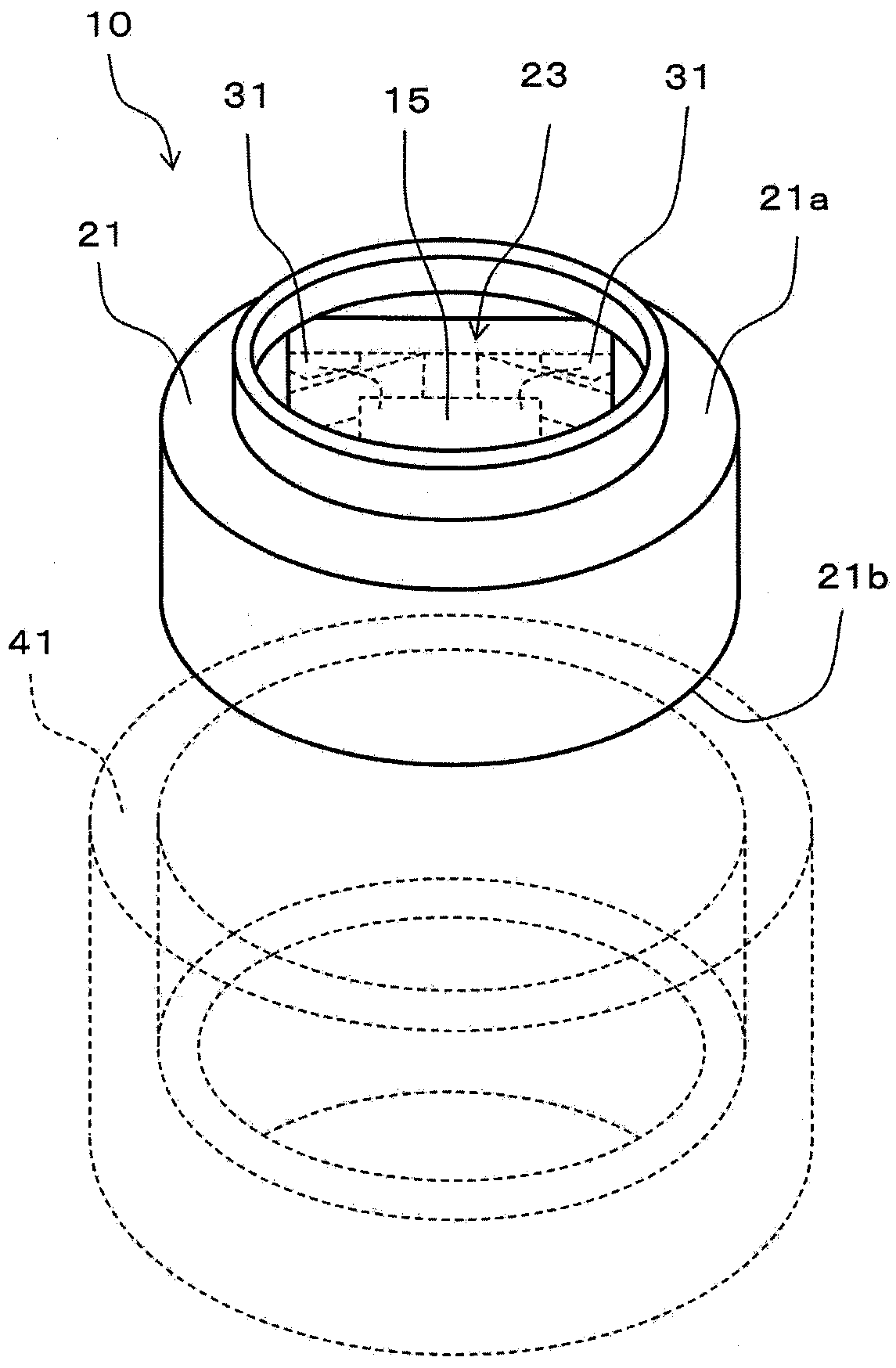
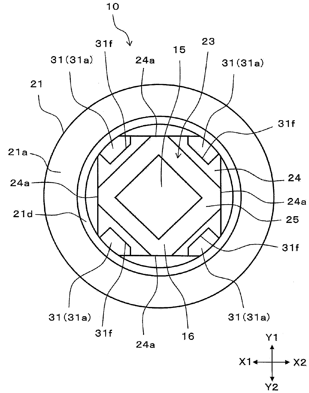
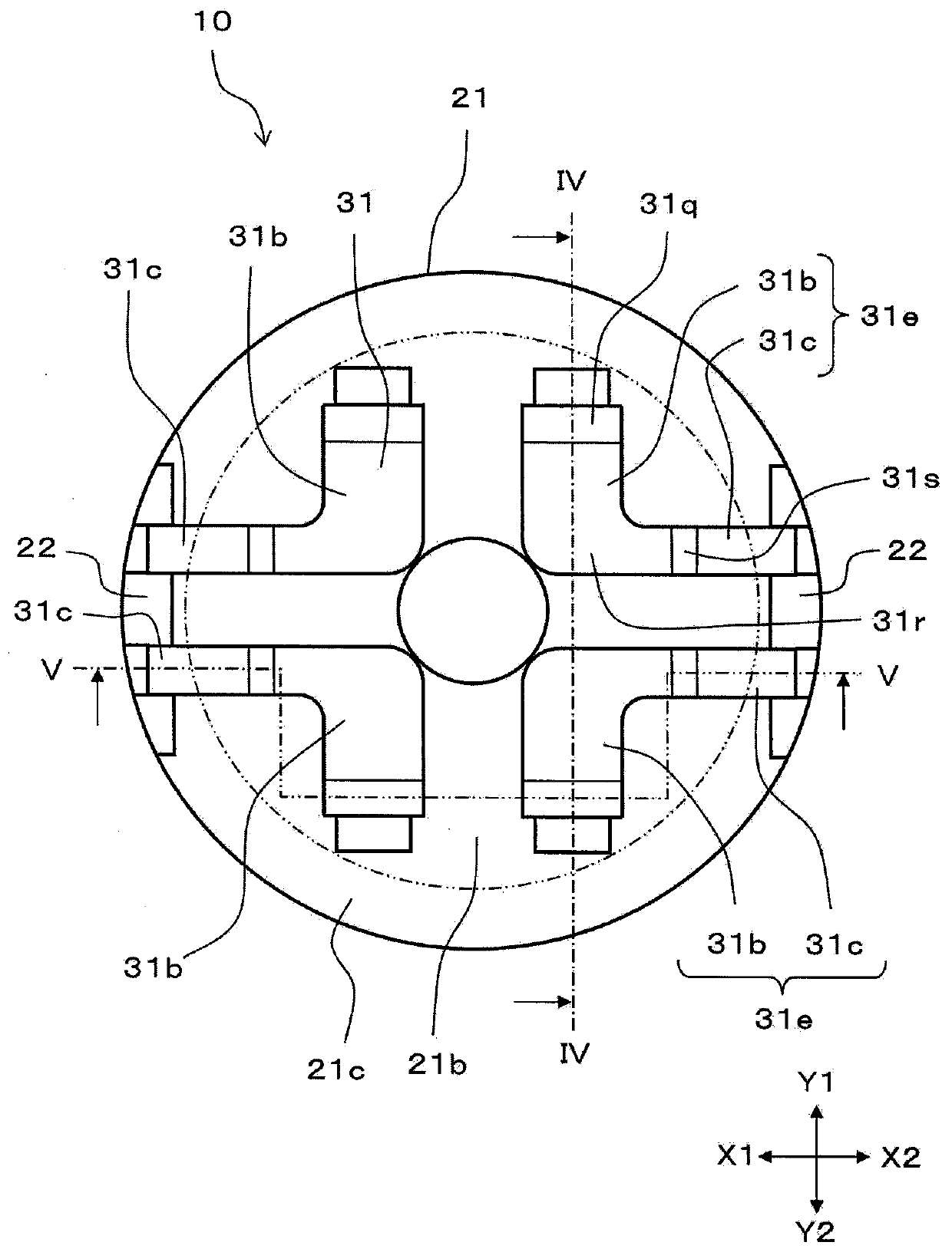
[0065] figure 1 It is a perspective view of the pressure detection device of the embodiment. figure 2 is the top view of the pressure detection device, image 3 It is the bottom view of the pressure detection device. and, Figure 4 so image 3 The cross-sectional view of the pressure detection device when viewed from the direction of the arrow when the line IV-IV is cut. Figure 5 is from with Figure 4 The cross-sectional views observed in different directions are based on image 3 The cross-sectional view of the pressure detection device when the V-V line is cut and viewed from the direction of the arrow.

[0066] Such as figure 1 As shown, the pressure detection device 10 of this embodiment has: a casing 21 formed with a cavity 23; a pressure sensor 15 prov...


PUM


Abstract

The present invention provides a pressure detection device which can process lead frames through a simple and easy process and can guarantee the welding area. The characteristics of the pressure detection device are that: the pressure detection device includes a housing (21) with a chamber (23), a pressure sensor (15) in the chamber (23), and a plurality of lead frames (31) buried in the housing (21); each of the plurality of lead frames (31) is provided with an upper lead frame (31a) which is exposed toward the chamber (23) and is electrically connected with the pressure sensor (15), a connection part (31d) which extends upward along the thickness direction of the housing (21), and an exposure part (31e); all the connection parts (31d) are configured adjacently; the upper lead frame (31a) is bended along the same direction from the connection part (31d); and the interval between the connection parts (31d) at the side of the upper lead frame (31a) is greater than the interval between the connection parts (31d) at the side of the exposure part (31e).

Description

technical field [0001] The invention relates to a pressure detection device, in particular to a structure of a lead frame electrically connected with a pressure sensor. Background technique [0002] Patent Document 1 below discloses an invention related to a pressure detection device (described in Patent Document 1 as a pressure sensor package) with high positional accuracy and waterproof performance of a lead frame. Figure 10 (a) is a top view of a conventional pressure detection device, Figure 10 (b) is a bottom view of a conventional pressure detection device. in addition, Figure 11 so Figure 10 (a) and Figure 10 (b) is a cross-sectional view taken along line XI-XI and viewed from the direction of the arrow. [0003] Such as Figure 10 (a) and Figure 11 As shown, the pressure detection device 110 of the conventional example has: a pressure sensor 115 for detecting pressure; a case 121 for accommodating the pressure sensor 115 ; and a lead frame 131 electrically co...

Claims


Application Information

Patent Timeline
Patent Type & Authority Patents(China)
IPC IPC(8): H01L23/28H01L23/495
CPCH01L2224/48091H01L2224/48247
Inventor 大川尚信臼井学石田弘中山一英上村秀树
Owner ALPS ALPINE CO LTD
Why Eureka
Try Eureka