Arc welding device and arc welding control method

A technology of arc welding and control method, applied in the direction of welding/welding/cutting articles, arc welding equipment, welding equipment, etc.

Active Publication Date: 2021-04-20
PANASONIC INTPROP MANAGEMENT CO LTD
View PDF11 Cites 0 Cited by
  • Summary
  • Abstract
  • Description
  • Claims
  • Application Information

AI Technical Summary

Problems solved by technology

[0012] The prior art arc welding control method repeats the cycle of the short circuit period and the arc period described above

Method used


Image

  • Arc welding device and arc welding control method
  • Arc welding device and arc welding control method
  • Arc welding device and arc welding control method

Examples


Embodiment approach 1

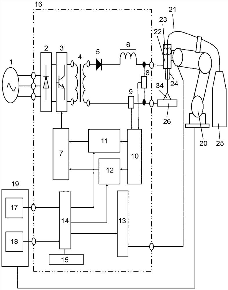
[0050] figure 1 The schematic structure of the arc welding apparatus in this Embodiment 1 is shown in . figure 1 Among them, the welding power supply device 16 is an arc welding device for welding the object to be welded by alternately repeating the short-circuit period TS during which the welding wire 21 and the object to be welded 26 are short-circuited, and the arc period TA during which the short circuit is disconnected and an arc is generated. Rectification part 2, switch part 3, transformer 4, secondary rectification part 5, reactor 6 (also referred to as DCL). The primary rectification unit 2 rectifies the output of the input power source 1 . The switch unit 3 controls the welding output by controlling the output of the primary rectifying unit 2 . The transformer 4 insulates and converts the electric power from the switch unit 3 . The secondary rectification unit 5 rectifies the secondary side output of the transformer 4 . Reactor 6 is connected in series with sec...


PUM


Abstract

Equipped with: a storage unit (15), storing a group corresponding to the short-circuit frequency, peak current, and peak current period; and a determination unit (14), based on the set short-circuit frequency and the group stored in the storage unit (15). , to determine the peak current as well as the peak current period. The welding output unit performs welding output based on the peak current and peak current period determined by the determination unit (14).

Description

technical field [0001] The present invention relates to an arc welding device and an arc welding control method that repeat forward feed and reverse feed as feeding of a consumable electrode, that is, a welding wire, and alternately generate a short-circuit state and an arc state for welding. Background technique [0002] In the case of welding galvanized steel sheets, generally, short-circuit transition welding (CO 2 welding, MAG welding), pulsed MAG welding are widely used. Figure 8 It is a diagram for explaining a conventional arc welding control method for welding galvanized steel sheets. [0003] The boiling point of the galvanized zinc plated on the surface of the galvanized steel sheet is 907 degrees, which is 1536 degrees lower than the melting point of iron. When arc welding is performed on a galvanized steel sheet, zinc vaporizes, and this zinc vapor diffuses to the outside through the molten metal in the molten pool. However, when the solidification rate of the...

Claims


Application Information

Patent Timeline
Patent Type & Authority Patents(China)
IPC IPC(8): B23K9/073B23K9/12
CPCB23K9/073B23K9/093B23K9/0953B23K9/1031B23K9/1037B23K9/1062B23K9/124B23K9/173B23K9/23B23K2101/18B23K2101/34B23K9/025B23K2103/166B23K9/16
Inventor 藤原润司川本笃宽古山雄也
Owner PANASONIC INTPROP MANAGEMENT CO LTD
Why Eureka
Try Eureka