
Anti-bending friction support
An anti-buckling, friction-energy-consuming technology, applied in earthquake-proofing, building components, etc., can solve the problems of friction damper buckling failure, complex node connection structure, improper support design, etc., to achieve good durability and reduce economic and social impact. , the effect of easy acquisition
- Summary
- Abstract
- Description
- Claims
- Application Information
AI Technical Summary
Problems solved by technology
Method used
Image

Examples
Embodiment 1
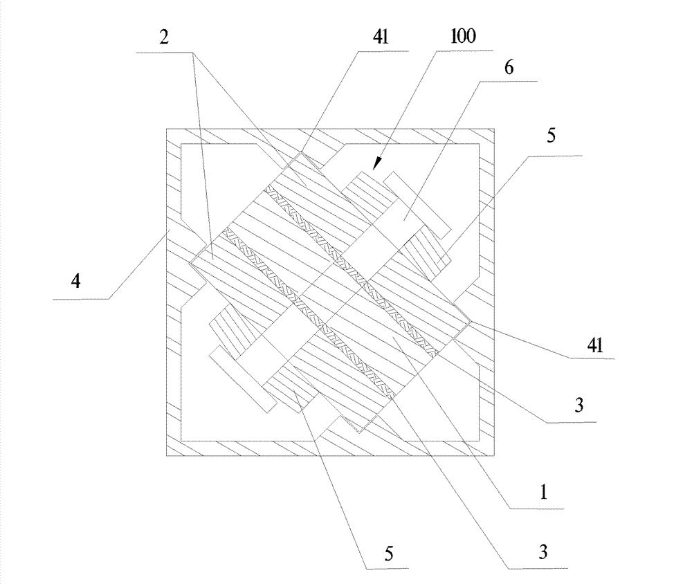
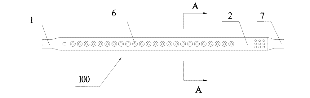
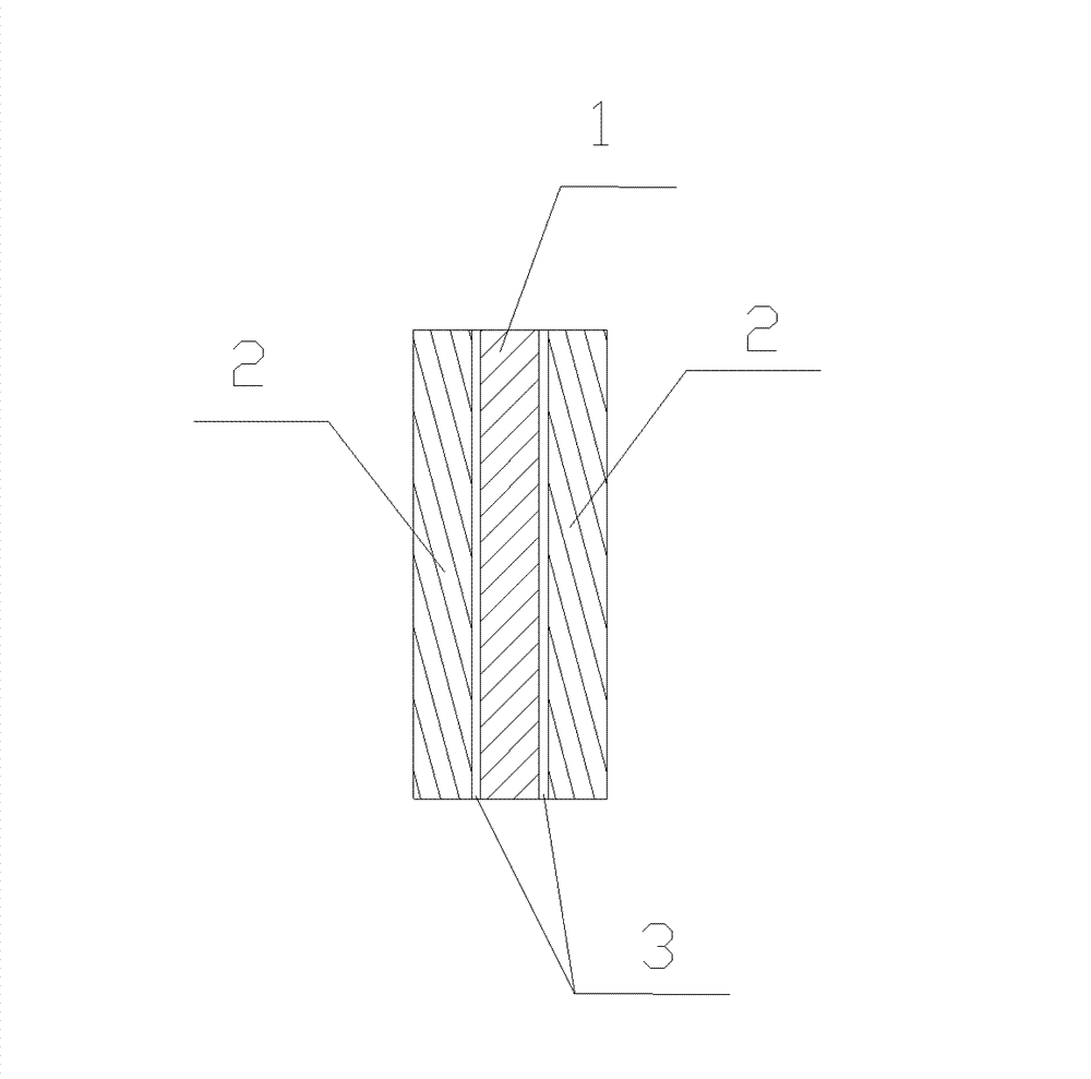
[0034] Such as Figure 1-Figure 5 As shown, the Buckling-Restrained Friction Brace (BRFB for short) of Embodiment 1 of the present invention includes a buckling-restrained outer shell 4 for support and a frictional energy-dissipating core 100 located in the buckling-resistant outer shell 4; In an example, the friction energy dissipation core 100 includes two second steel plates 2 and a first steel plate 1 sandwiched between the two second steel plates 2, and friction materials 3 are attached to both sides of the first steel plate 1; A strip chute 12 is provided along the length direction of the first steel plate 1, and a plurality of connecting holes 21 opposite to each other are provided on two second steel plates 2; the friction energy dissipation core 100 passes through the connecting holes 21 It is connected with a plurality of connecting pieces 6 of the bar-shaped chute 12. In this embodiment, the connecting pieces 6 are bolts. Of course, other connecting pieces can also ...
Embodiment 2
[0043] Such as Figure 10 , Figure 11 As shown, the difference between Embodiment 2 and Embodiment 1 is that the first steel plate 1 is fixedly connected with a plurality of purlins on one side for adhering the friction material 3, and the height of the purlins protruding from the first steel plate is slightly smaller than that of the friction material 3. As long as the deformation space generated by the pre-pressure is left.
[0044] In this embodiment, the purlins can be steel bars welded on the surface of the first steel plate 1, and before the friction material 3 is attached to the first steel plate 1, the purlins are first welded, and then the friction material 3 is attached to the surface of the first steel plate 1, and the purlins It can help the friction material 3 bear compressive stress and shear stress, and prevent the friction material 3 from falling off or being extruded under the action of a large pre-pressure. Such as Figure 11 As shown, in this implementat...
PUM
 Abstract
Description
Claims
Application Information