Laser azimuth instrument
An azimuth and laser technology, applied in the field of laser azimuth, can solve the problem of low measurement accuracy and achieve the effect of high accuracy and simple operation
- Summary
- Abstract
- Description
- Claims
- Application Information
AI Technical Summary
Problems solved by technology
Method used
Image
Examples
Embodiment 1
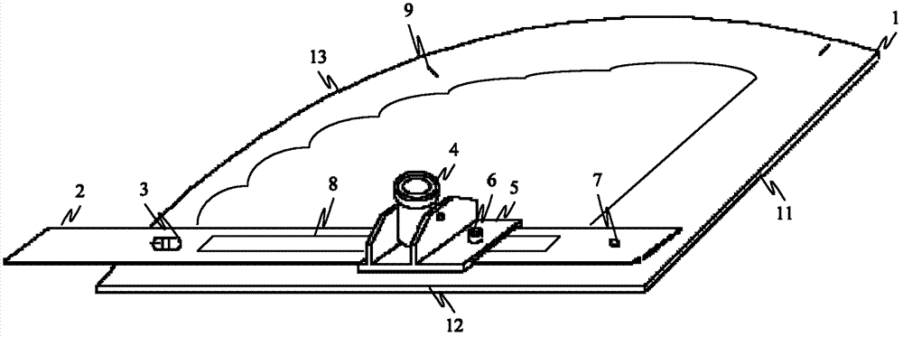
[0017] Such as figure 1 As shown, the embodiment of the present invention provides a kind of laser azimuth instrument, and this laser azimuth instrument is made of angle ruler 1, ruler 2, sliding seat, laser instrument 4 and level instrument 6; Angle ruler is a sector frame, and this sector frame is composed of radial The frame 11, the arc-shaped frame 13 and the radial frame 12 are surrounded by (in this embodiment, integrally formed), the angle between the radial frame 11 and the radial frame 12 can be between 0 degrees and 180 degrees, Specifically, it is 30 degrees, 60 degrees, 90 degrees, 120 degrees, 150 degrees, etc., which can be selected according to the angle to be adjusted. The arc frame 9 forming the fan-shaped frame is provided with a scale, and the scale 2 is a strip-shaped plate with one end of the scale 2 Rotatingly connected with the center of the fan-shaped frame, the other end of the scale is provided with an observation hole 3 corresponding to the scale; th...
Embodiment 2
[0020] Such as Figure 6-8 As shown, as a further improvement of Embodiment 1, in order to reduce the calculation, the angle reading observed through the observation hole 3 is the angle between the drill body 10 and the center line, so that the reading is more intuitive, and the fan-shaped frame The central angle is 90 degrees, that is, the angle between the radial frame 11 and the radial frame 12 is 90 degrees. During use, the radial frame 11 of the 90-degree scale is attached to the rig body 10, i.e. c=90, a=b is obtained by a=90+b-c, and the angle b read from the observation hole 3 is The angle a between the drill body and the center line is more convenient to use and saves calculation.
[0021] The scale 2 is rotatably connected with the angle ruler 1 through a pin shaft 7 . Such as Figure 4 As shown, the bottom of the base plate 5 is provided with a chute 52 , and the scale 2 is placed in the chute 52 . The structure is simple and easy to manufacture.
PUM
 Abstract
Description
Claims
Application Information
 - R&D
- Intellectual Property
- Life Sciences
- Materials
- Tech Scout
- Unparalleled Data Quality
- Higher Quality Content
- 60% Fewer Hallucinations
Browse by: Latest US Patents, China's latest patents, Technical Efficacy Thesaurus, Application Domain, Technology Topic, Popular Technical Reports.
© 2025 PatSnap. All rights reserved.Legal|Privacy policy|Modern Slavery Act Transparency Statement|Sitemap|About US| Contact US: help@patsnap.com


