
Magneto-rheological pump type variable-damping shock absorber

A magnetorheological and shock absorber technology, used in shock absorbers, liquid shock absorbers, shock absorbers, etc., can solve the problem that the shock absorber cannot reduce the vibration performance, cannot achieve the vibration reduction effect, and the sealing element fails. problem, to achieve the effect of sensitive vibration response, avoid premature failure, and simple structure

Active Publication Date: 2013-05-08
浙江孔辉汽车科技有限公司
View PDF7 Cites 14 Cited by
  • Summary
  • Abstract
  • Description
  • Claims
  • Application Information

AI Technical Summary

Problems solved by technology

When the road condition of the vehicle is beyond the adaptable range, the damping force will be too large or too small to achieve the matching damping effect, and the damping performance of the shock absorber cannot be adjusted according to the working conditions during the driving process of the vehicle. Automatic adjustment is required; moreover, the structure of the valve parts used is complex, the oil cannot circulate in the working cylinder, the heat dissipation effect is poor, and the sealing components often fail prematurely due to the influence of excessive temperature

Method used


Image

  • Magneto-rheological pump type variable-damping shock absorber
  • Magneto-rheological pump type variable-damping shock absorber
  • Magneto-rheological pump type variable-damping shock absorber

Examples


Embodiment approach 2

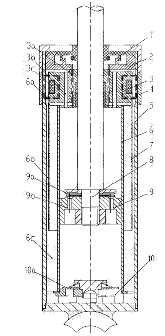
[0024] see Figure 5 , is the second embodiment of the present invention, the electromagnetic coil 3c is installed on the guide 3, and the effective magnetic field is divided into two parts: one part is concentrated between the oil seal seat 2 and the upper end surface of the guide 3; the other part is concentrated on the outer cylinder 5, Between the side of the wind deflector 7 and the guide 3.

[0025] see Figure 6 , is the third embodiment of the present invention, three (or more) electromagnetic coils 3c are installed on the guide 3, and the effective magnetic field is concentrated between the outer cylinder 5, the shroud 7 and the side of the guide 3.

[0026] see Figure 7 , is Embodiment 4 of the present invention, three (or more) electromagnetic coils 3c are installed on the guider 3, Embodiment 4 combines the characteristics of Embodiment 2 and Embodiment 3, and the effective magnetic field is divided into two parts: one part concentrates Between the oil seal sea...


PUM


Abstract

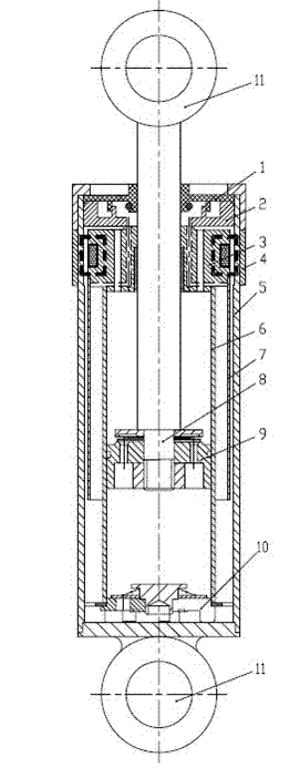
The invention relates to a magneto-rheological pump type variable-damping shock absorber suitable for various vehicle suspension systems. The shock absorber is provided with an outer cylinder barrel with packaged upper and lower sides, wherein a hydraulic working cylinder is arranged in the outer cylinder barrel; the working cylinder is internally provided with a piston with a circulating hole, a piston rod connected to the piston and a stopper; the lower port of the working cylinder is connected to a bottom valve seat; a guider and an oil seal base connected to the guider are connected to the upper port of the working cylinder; the guider is internally provided with one or more electromagnetic coils; a magneto-rheological liquid flow guide hood is arranged between the working cylinder and the outer barrel wall; a gap between the outer wall of the flow guide hood and the inner wall of the outer cylinder barrel forms an annular return oil channel; and a damping one-way valve is respectively arranged at the liquid flow channel openings of both the bottom valve seat and the piston. The shock absorber is internally filled with a magneto-rheological liquid, so that the yield stress of the shock absorber increases monotonically along with the enhancement of the magnetic field; due to the damping characteristic of the shock absorber, the shocker absorber can adapt to the needs of vibration damping performances of various road surface conditions through the adjustment of the intensity of the current in the coils, and particularly, can avoid impact of large-amplitude and strong vibration of a car on a rugged road. The magneto-rheological pump type variable-damping shock absorber has the advantages of a rational design, a simple structure, strong working reliability, good damping effects and long service life.

Description

technical field [0001] The invention belongs to the technical field of configuration of vehicle suspension devices, and relates to a magneto-rheological pump type variable damping shock absorber suitable for various vehicle suspension systems. Background technique [0002] Common shock absorbers for vehicle suspensions are provided with extension valves, compression valves, compensation valves and flow valves. When the frame (or load-bearing body) moves relative to the axle, the piston of the shock absorber will reciprocate in the cylinder, and the oil in the working chamber will pass through the valve systems, thereby generating damping force to attenuate the Ground and engine vibration and shock. The size of its damping depends on the elasticity of each valve piece group; once each valve piece group is adjusted and installed, the damping characteristics of each valve part of the shock absorber and the damping performance of the shock absorber are determined, and its The ...

Claims


Application Information

Patent Timeline
Patent Type & Authority Applications(China)
IPC IPC(8): F16F9/18F16F9/53F16F9/34F16F9/42
Inventor 郭孔辉章新杰郭弓
Owner 浙江孔辉汽车科技有限公司
Learn More