A magneto-rheological valve-controlled damping controllable shock absorber

A magneto-rheological valve and shock absorber technology, which is applied in the field of parts and components, can solve problems such as the inability to take into account both vehicle ride comfort and handling stability, the damping force cannot achieve the vibration reduction effect, and the failure of sealing components, so as to avoid temperature Too high and premature failure, sensitive vibration response, attenuation of vibration and shock effects

Active Publication Date: 2017-09-19
浙江孔辉汽车科技有限公司
View PDF5 Cites 0 Cited by
  • Summary
  • Abstract
  • Description
  • Claims
  • Application Information

AI Technical Summary

Problems solved by technology

When the road surface conditions change beyond the adaptable range of the suspension system, the damping force will be too large or too small to achieve the best damping effect, and it cannot be automatically adjusted according to the change of working conditions, so the ride comfort of the vehicle cannot be taken into account at the same time and handling stability; secondly, the structure of the valve parts used in the existing shock absorber is complex; and the oil does not circulate in the working cylinder and the heat dissipation is poor, which often leads to premature failure of the sealing element due to the influence of high temperature

Method used


Image

  • A magneto-rheological valve-controlled damping controllable shock absorber
  • A magneto-rheological valve-controlled damping controllable shock absorber
  • A magneto-rheological valve-controlled damping controllable shock absorber

Examples


Embodiment Construction

[0027] The technical features of a magneto-rheological valve-controlled damping controllable shock absorber of the present invention will be further described in conjunction with the accompanying drawings and embodiments:

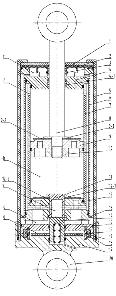
[0028] figure 1 It is a schematic diagram of the overall structure of an embodiment of the present invention. Its structure is simple. The damping force adjustment range and adjustment characteristics can be further adjusted by changing the size of the plane throttle valve port. Combined with the electronic control system, the control accuracy can be improved to ensure its working stability. .

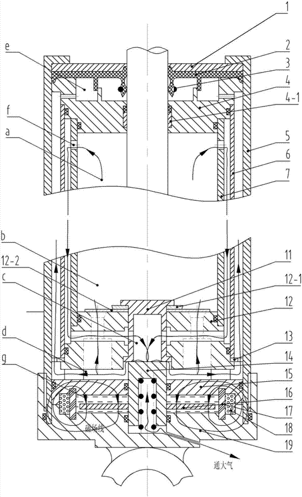
[0029] like figure 1 As shown, the shock absorber mainly includes a guide assembly 4, an oil storage cylinder 5, an intermediate cylinder 6, a working cylinder 7, a piston rod 8, a piston valve assembly composed of a piston 9 and an internally threaded piston fixing block 10, and a bottom valve The assembly 12 and the magnetorheological valve composed of the magne...


PUM


Abstract

A magnetorheological valve control damping-controllable shock absorber comprises a work cylinder, a middle cylinder, an oil storage cylinder, a guiding device assembly, a piston valve assembly, a base valve assembly and a magnetorheological valve assembly; the work cylinder is installed in an inner cavity of the oil storage cylinder; the bottom end of the work cylinder is connected with the bottom valve assembly; the guiding device assembly is installed at the upper end of the work cylinder; the piston valve assembly and a piston rod connected with the piston valve assembly are installed in an inner cavity of the work cylinder; the middle cylinder is located in a cavity between the oil storage cylinder and the work cylinder, and a gap between the middle cylinder and the work cylinder forms an oil channel; a circulating hole communicating with the middle cylinder is formed in the upper end of the work cylinder; the lower end of the middle cylinder is matched with the bottom valve assembly; a cavity among the oil storage cylinder, the middle cylinder and the guiding device assembly forms an oil storage cavity; and the magnetorheological valve assembly is installed below the bottom valve assembly and is fixedly connected with the outer wall of the oil storage cylinder. The shock absorber is compact in structure, easy to machine, low in cost, easy to tool and capable of achieving continuous and controllable damping according to different driving work conditions of a vehicle.

Description

technical field [0001] The invention relates to a component used in a vehicle suspension system, in particular to a magneto-rheological valve-controlled damping controllable shock absorber. Background technique [0002] Common shock absorbers for vehicle suspension are provided with a recovery valve, a compression valve, a compensation valve and a flow valve. The damping of the shock absorber depends on the elasticity of each valve group. Once the valve groups are adjusted and installed, the damping characteristics of each valve part and the overall damping performance of the shock absorber will be determined accordingly. Therefore, The ability of the suspension system to adapt to changes in road conditions is also determined. When the road conditions change beyond the adaptable range of the suspension system, the damping force will be too large or too small to achieve the best damping effect, and it cannot be automatically adjusted according to the change of working condit...

Claims


Application Information

Patent Timeline
Patent Type & Authority Patents(China)
IPC IPC(8): F16F9/53F16F9/34F16F9/42F16F9/32
CPCF16F9/3207F16F9/34F16F9/42F16F9/537F16F2222/12
Inventor 郭孔辉王杨韩忠良
Owner 浙江孔辉汽车科技有限公司
Why Eureka
Try Eureka