Novel double balance reducer for pumping units

A technology of double balance and reducer, which is applied in the direction of mechanical equipment, transmission parts, gear transmission, etc., can solve the problems of laborious energy consumption of large horse-drawn carts, large fluctuations in net torque curve, and poor power supply quality of the power grid, etc., to achieve Avoid large horse-drawn carts, improve motor efficiency, and reduce the effect of power configuration

Inactive Publication Date: 2013-05-08
NORTHEAST GASOLINEEUM UNIV
View PDF4 Cites 4 Cited by
  • Summary
  • Abstract
  • Description
  • Claims
  • Application Information

AI Technical Summary

Problems solved by technology

[0002] At present, conventional beam pumping units adopt crank balance or compound balance based on crank balance. The balance torque generated by the crank balance device on the output shaft of the reducer changes according to the sinusoidal law. After the load torque curve and the crank balance torque curve are reduced , even in an ideal balanced state, there are still problems with large net torque curve fluctuations, high peaks and deep negative valleys, so it is necessary to choose a reducer with a larger torque and a motor with a higher power, resulting in large The laborious energy consumption of the horse-drawn trolley makes the efficiency of the pumping unit low and the energy consumption is serious, and the motor works in a state of low power factor, which will also make the power supply quality of the grid much worse

Method used


Image

  • Novel double balance reducer for pumping units
  • Novel double balance reducer for pumping units
  • Novel double balance reducer for pumping units

Examples


Embodiment Construction

[0010] The application will be further explained below in conjunction with the drawings:

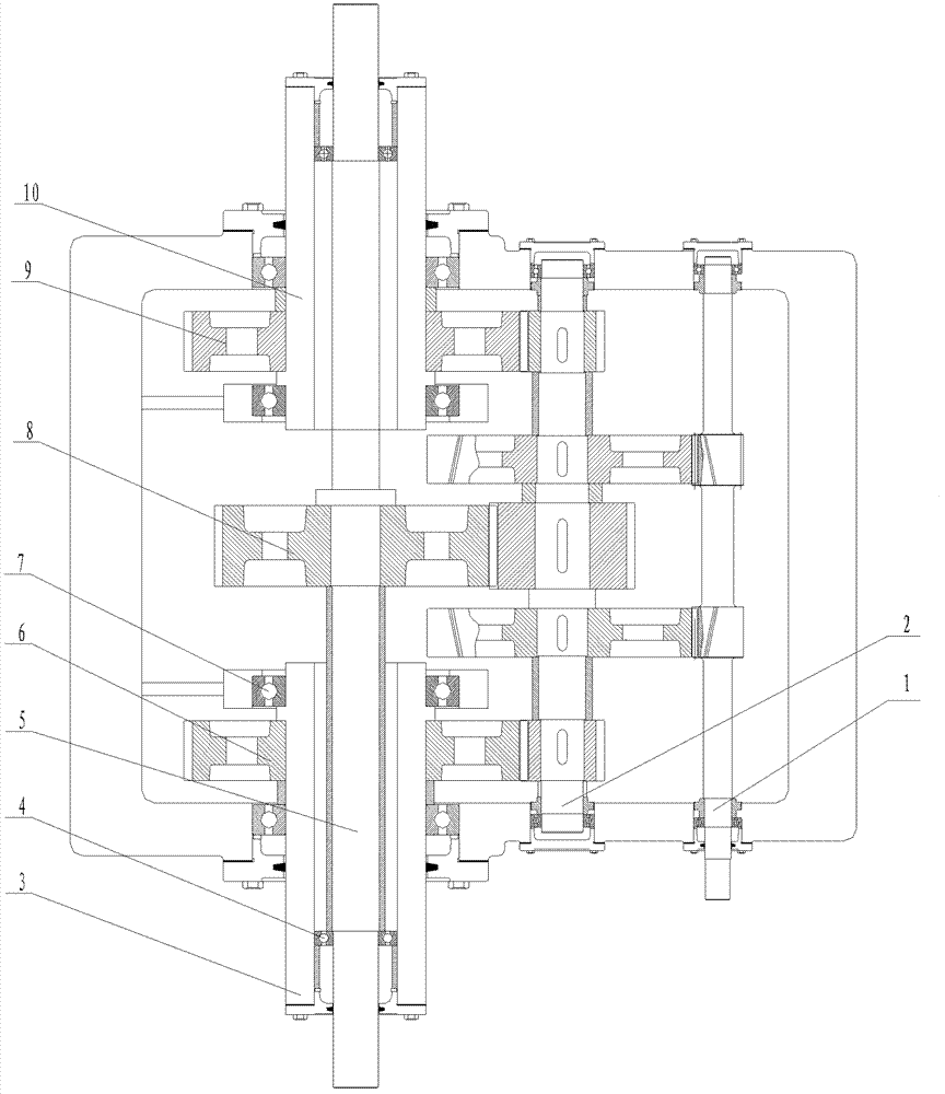
[0011] by figure 1 Shown: The new double-balanced reducer for pumping units adopts two-stage transmission, including input shaft 1, intermediate shaft 2, and output shaft. The structure of input shaft 1 and intermediate shaft 2 and the transmission mode between the two are adopted It is a conventional technology; the technical innovation of the reducer of this application is the use of a new structure of the output shaft, the output shaft is composed of a first hollow shaft 3, a second hollow shaft 10 and a solid shaft 5, the solid shaft 5 Deep groove ball bearings 4 are installed at both ends. The solid shaft 5 is supported by these two deep groove ball bearings 4 and positioned in the first hollow shaft 3 and the second hollow shaft 10. The center of the solid shaft 5 is connected to the first hollow shaft with a key. Transmission gear 7; the other two idler shafts are respectively suppor...


PUM


Abstract

The invention provides a novel reducer for pumping units and solves the problem that the existing motor for pumping units operates under low power factor. An output shaft of the reducer comprises a hollow shaft and a solid shaft. The hollow shaft and the solid shaft are connected with a secondary balance weight and a primary crank balance weight in a pumping unit respectively. Speed ratio of the hollow shaft to the solid shaft is 1:2. When the pumping unit is in upward stroke, the motor, the primary crank balance weight and the secondary balance weight pull a sucker rod to move up. When the pumping unit is in downward stroke, the motor, the secondary balance weight and a sucker rod weight pull the primary crank balance weight to move up. Therefore, power configuration of the motor is reduced greatly, pulling small cars with high horsepower is avoided, motor efficiency is improved, and energy consumption is lowered.

Description

technical field [0001] The invention relates to a speed reducer, in particular to a speed reducer applied to a pumping unit. Background technique [0002] At present, conventional beam pumping units adopt crank balance or compound balance based on crank balance. The balance torque generated by the crank balance device on the output shaft of the reducer changes according to the sinusoidal law. After the load torque curve and the crank balance torque curve are reduced , even in an ideal balanced state, there are still problems with large net torque curve fluctuations, high peaks and deep negative valleys, so it is necessary to choose a reducer with a larger torque and a motor with a higher power, resulting in large The laborious energy consumption of the horse-drawn trolley makes the efficiency of the pumping unit low and the energy consumption is serious, and the motor works in a state of low power factor, which will also make the power supply quality of the grid deteriorate ...

Claims


Application Information

Patent Timeline
Patent Type & Authority Applications(China)
IPC IPC(8): F16H1/22F16H57/021F16H57/023
Inventor 梁宏宝陈颖王岩梁宇宁孟庆伟才松林
Owner NORTHEAST GASOLINEEUM UNIV
Why Eureka
Try Eureka