Transmission mechanical movement device

A motion device, transmission machinery technology, applied in the direction of transmission device, transmission box, mechanical equipment, etc., can solve the problems of low transmission efficiency, high noise, wear and other problems, and achieve the effect of single force, small wear, efficient and stable operation

Active Publication Date: 2015-10-28
OCEANKING DONGGUAN LIGHTING TECH +2
View PDF3 Cites 0 Cited by
  • Summary
  • Abstract
  • Description
  • Claims
  • Application Information

AI Technical Summary

Problems solved by technology

[0002] At present, transmission machinery is widely used in the mechanical field. In order to realize the horizontal and vertical movement of the transmission machinery movement device, the general transmission machinery movement device is driven by means of a worm gear. The worm gear transmission structure is relatively compact, but its transmission efficiency is low. Serious wear, vibration and noise during transmission

Method used


Image

  • Transmission mechanical movement device
  • Transmission mechanical movement device
  • Transmission mechanical movement device

Examples


Embodiment Construction

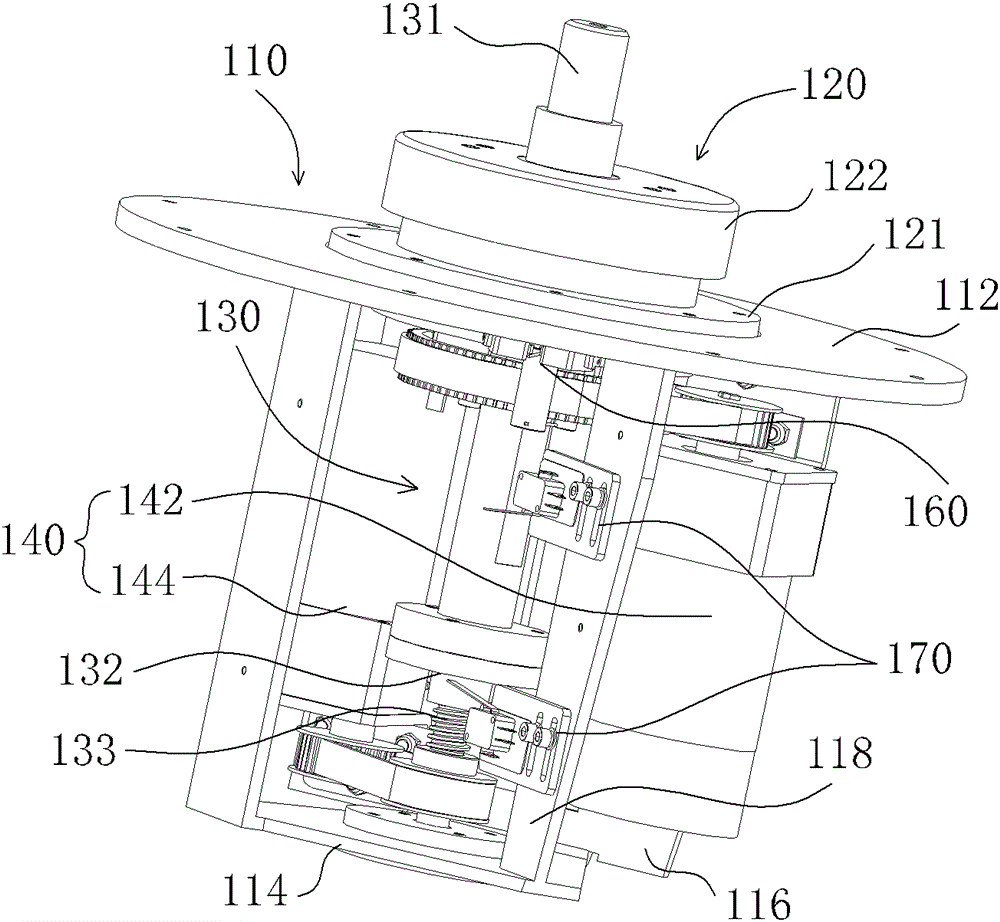
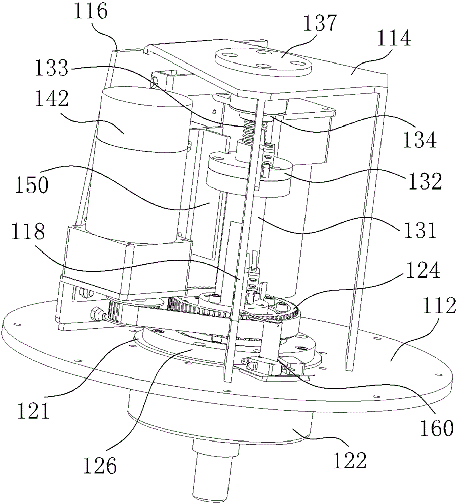
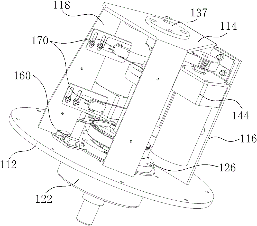
[0020] In order to solve the problems of low transmission efficiency, serious wear and unstable transmission, a high-efficiency and stable transmission mechanical motion device is proposed.

[0021] Such as figure 1 , figure 2 and image 3 As shown, the transmission mechanical movement device of the preferred embodiment of the present invention includes a mounting frame 110 , a rotating mechanism 120 , a lifting mechanism 130 and a motor 140 . The installation frame 110 includes a top plate 112 and a bottom plate 114 , and coaxial top plate holes and bottom plate holes are opened on the top plate 112 and the bottom plate 114 . The rotating mechanism 120 is installed in the top plate hole. One end of the lifting mechanism 130 is installed in the hole of the bottom plate, and the other end passes through the hole of the top plate and can move up and down along the axial direction of the hole of the top plate. The motor 140 is installed on the mounting frame 110. The motor 1...


PUM


Abstract

A transmission machinery movement device comprises a mounting rack, a rotating mechanism, a lifting mechanism and a motor. The mounting rack comprises a top plate and a bottom plate. The top plate and the bottom are provided with a top plate hole and a bottom plate hole which are coaxial. The rotating mechanism is disposed in the top plate hole. One end of the lifting mechanism is disposed in the bottom plate hole, the other end of the lifting mechanism penetrates through the top plate hole, and the lifting mechanism is capable of moving up and down axially along the top plate hole. The motor is used for driving the lifting mechanism to move up and down and driving the rotating mechanism to rotate. The transmission machinery movement device is available for efficient, stable rotation, and low in wear. In addition, the whole transmission machinery movement device is installed on the mounting rack, installation space is fully economized, and compactness of the whole transmission machinery movement device is kept.

Description

【Technical field】 [0001] The invention relates to a transmission mechanical device, in particular to a transmission mechanical movement device. 【Background technique】 [0002] At present, transmission machinery is widely used in the mechanical field. In order to realize the horizontal and vertical movement of the transmission machinery movement device, the general transmission machinery movement device is driven by means of a worm gear. The worm gear transmission structure is relatively compact, but its transmission efficiency is low. The wear is serious, and vibration and noise will be generated during the transmission process. 【Content of invention】 [0003] Based on this, it is necessary to provide a transmission mechanical motion device capable of efficient and stable transmission. [0004] A transmission mechanical motion device, comprising a mounting frame, a rotating mechanism, a lifting mechanism and a motor, the mounting frame includes a top plate and a bottom pl...

Claims


Application Information

Patent Timeline
Patent Type & Authority Patents(China)
IPC IPC(8): F16H57/02F16H37/02
Inventor 周明杰李鹏飞
Owner OCEANKING DONGGUAN LIGHTING TECH
Why Eureka
Try Eureka