Stress-free pipe gallery system

A stress-free, pipe gallery technology, applied in the direction of pipe components, pipe supports, pipes/pipe joints/fittings, etc., can solve the problems of small compensation distance, high operating cost, long construction period, etc. The effect of large span of pipe gallery and convenient arrangement of branch pipes

Active Publication Date: 2019-02-22
JIANGSU HONGXIN PIPELINE ENG DESIGN CO LTD
View PDF6 Cites 0 Cited by
  • Summary
  • Abstract
  • Description
  • Claims
  • Application Information

AI Technical Summary

Problems solved by technology

[0011] The purpose of the present invention is to design a non-thrust, Stress-free pipe gallery system with high safety, low cost, convenient construction and short construction period

Method used


Image

  • Stress-free pipe gallery system
  • Stress-free pipe gallery system
  • Stress-free pipe gallery system

Examples


Embodiment 1

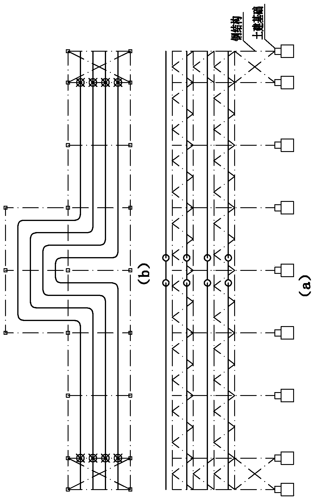
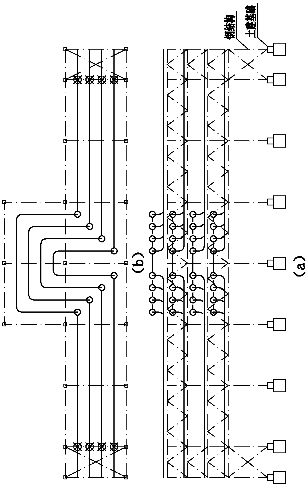
[0043] Such as Figure 7 , 9 shown.

[0044] A stress-free pipe gallery system, which is composed of several pipes 1 installed on the support 2, and each pipe 1 installed on the support 2 is evenly spaced with a length compensation mechanism 3 for preventing its thermal expansion and contraction from being damaged. The length between adjacent length compensating mechanisms 3 can be more than 60 meters, wherein more than 200 meters is the most economical, and the longest can reach 500 meters. Each length compensation mechanism 3 is composed of four rotary compensators 5 and connecting pipe fittings 6. The connecting pipe fittings 6 are composed of elbows 601 and connecting pipes 602. In order to save floor space, each length compensation mechanism is arranged in a misplaced position, occupying only a height The space reduces the horizontal footprint, making the extension meter very small, only one-third to one-tenth of the extension meter of the traditional pipe gallery. Fi...

Embodiment 2

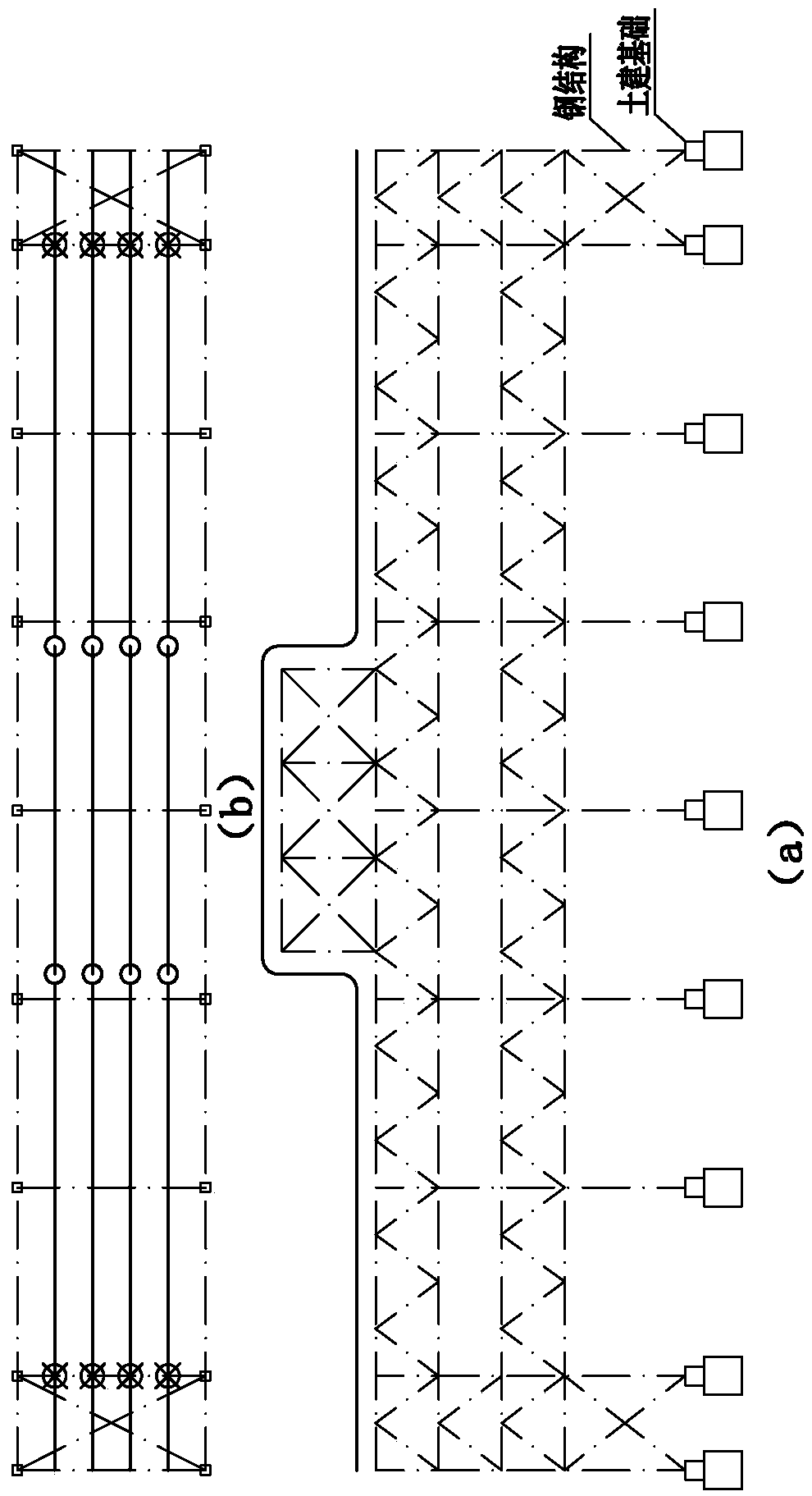
[0050] Such as Figure 8 shown.

[0051] The difference between this embodiment and Embodiment 1 is that the support 2 for the movable supporting pipeline is canceled, and the suspension frame with a suspension cable is used instead of the support. The pipeline is laid flat on the frame structure, and the frame structure can be a single-layer or multi-layer structure. The suspension tower can be built between two length compensation mechanisms 3. This situation is suitable for lighter pipelines and larger length compensation mechanisms (such as 400 meters, 500 meters, etc.), when adjacent length compensation mechanisms 3 When the distance is small, the suspension tower and the fixed bracket of the length compensation mechanism can also be directly combined into one.


PUM


Abstract

A stressless pipe rack system comprises several pipes (1) mounted on frames (2). Each of the pipes (1) mounted on the frames (2) is provided with a length compensation mechanism (3) at intervals, and used to prevent pipes from damage due to thermal expansion and cold contraction. The stressless pipe rack system is characterized in that: the length compensation mechanism (3) comprises four rotary compensators (5) and a connection pipe (6); all the pipes (1) are movably supported by the frames (2) fixed on ground so as to be replaced and maintained; the length compensation mechanism (3) is fixed at least along a pipe length direction on a compensation mechanism mounting frame (4), namely, the length compensation mechanism (3) cannot move along the pipe length direction on the compensation mechanism mounting frame (4); and the compensation mechanism mounting frame (4) is fixedly mounted on ground foundation. The present invention generates no stress in an operation process, and employs a long compensation distance and a simple structure, resulting in a low cost and high efficiency.

Description

technical field [0001] The invention relates to petrochemical pipeline installation technology, especially a petrochemical and oil and gas pipeline gallery structure, specifically a structure that uses a rotary compensator as a compensation unit, and only has gravity load on the pipeline system, no axial load (pipeline) thrust in the length direction) stress-free pipe gallery system. Background technique [0002] There are five ways to arrange pipes on the traditional pipe gallery, such as Figure 1-6 As shown, they all adopt natural compensation, the stress of the pipeline is large, the structure of the pipe gallery is complicated, the amount of steel is large, and the cost is high. [0003] ①The amount of compensation is small, and a set needs to be set every 40-60m; [0004] ②In order to ensure sufficient compensation, the arm length of natural compensation needs to be very long, resulting in a large area of ​​civil construction, a large scale of civil construction, and ...

Claims


Application Information

Patent Timeline
Patent Type & Authority Patents(China)
IPC IPC(8): F16L51/00F16L27/12F16L3/22
CPCF16L51/00
Inventor 宋章根宋苏炜潘八庆张杰朱涛钟旭
Owner JIANGSU HONGXIN PIPELINE ENG DESIGN CO LTD
Why Eureka
Try Eureka