Detecting device for liquid flow of hollow turbine blade of combustion gas turbine

A technology for turbine blades and liquid flow, which is applied to mass flow measurement devices, direct mass flow meters, etc., can solve the problems of lack of accurate and reliable technical data, complicated operation, and loose sealing, etc., and achieves simple structure and simple processing. , Enhance the sealing effect

Active Publication Date: 2013-07-17
HARBIN TURBINE +1
View PDF5 Cites 0 Cited by
  • Summary
  • Abstract
  • Description
  • Claims
  • Application Information

AI Technical Summary

Problems solved by technology

[0003] The purpose of the present invention is to provide a gas turbine hollow turbine blade liquid flow detection device to solve the problems of poor sealing, unstable clamping and complicated operation of the current detection device, so that the detection cannot obtain accurate and reliable technical data.

Method used


Image

  • Detecting device for liquid flow of hollow turbine blade of combustion gas turbine
  • Detecting device for liquid flow of hollow turbine blade of combustion gas turbine
  • Detecting device for liquid flow of hollow turbine blade of combustion gas turbine

Examples


specific Embodiment approach 1

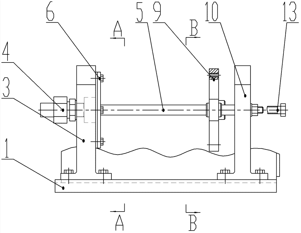
[0007] Specific implementation mode one: combine Figure 1-Figure 6 Describe this embodiment, the device of this embodiment includes a base 1, a left support 3, a straight-through pipe joint 4, a cover plate 6, a pressing plate 9, a right support 10, a jacking bolt 13 and a pair of guide rails 5, the base 1 is equipped with a left support 3 and a right support 10, the left support 3 and the right support 10 are arranged vertically, a pair of guide rails 5 are horizontally arranged between the left support 3 and the right support 10, and the pressing plate 9 is installed On a pair of guide rails 5 and slidingly connected with a pair of guide rails 5, a stepped through hole 3-1 is opened on the side wall of the left support 3, and one end of the straight-through pipe joint 4 is mounted on the left support 3 and communicated with the step. The hole 3-1 is connected, and the inner side wall of the left support 3 is equipped with a cover plate 6 and the two are detachably connected...

specific Embodiment approach 2

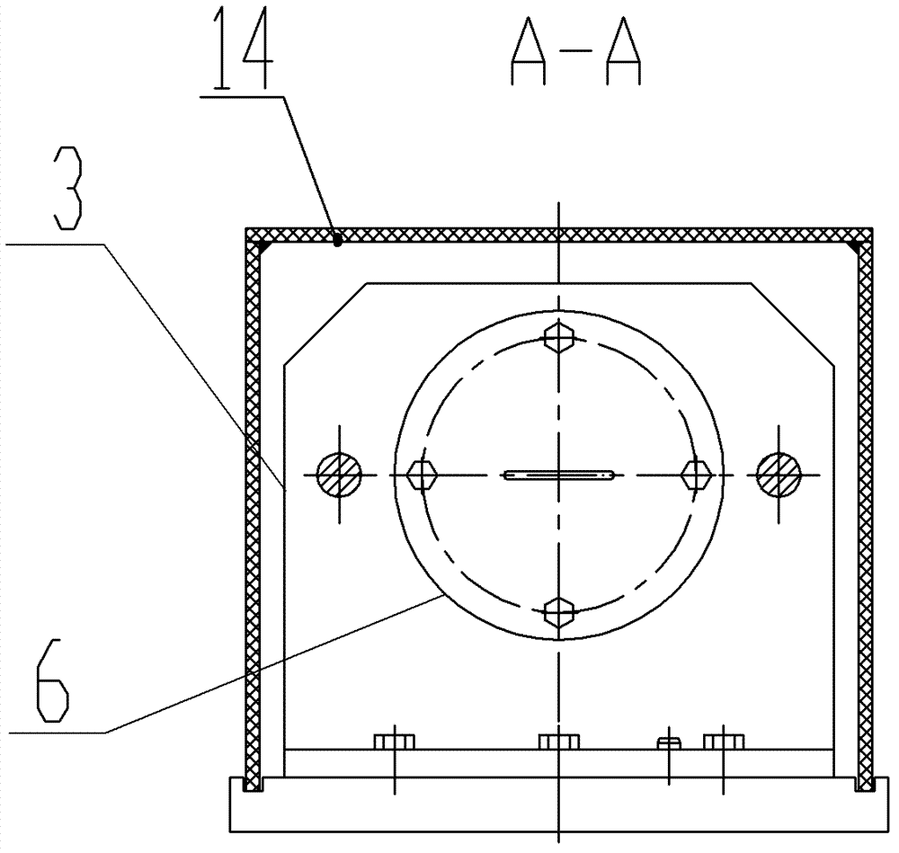
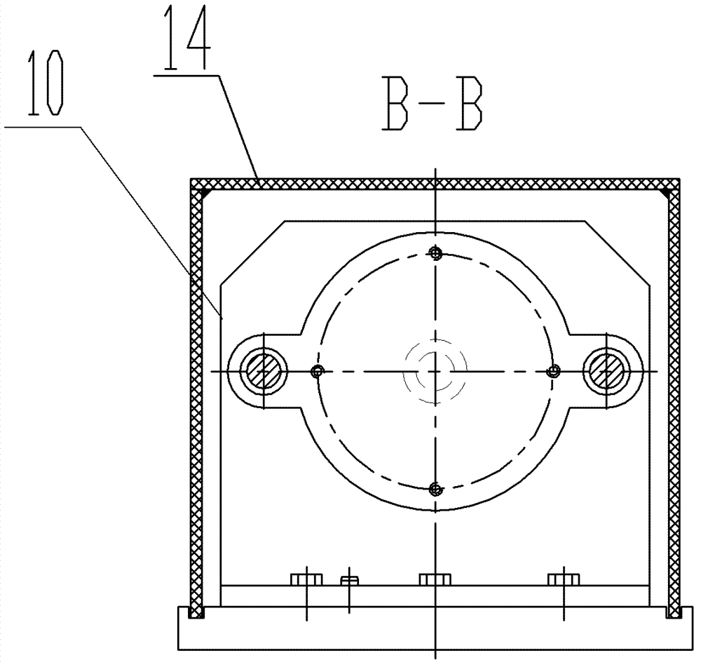
[0009] Specific implementation mode two: combination figure 2 Describe this embodiment, the device of this embodiment also includes a protective cover 14, a left support 3, a straight-through pipe joint 4, a cover plate 6, a pressing plate 9, a right support 10, a tightening bolt 13 and a pair of guide rails 5 All are arranged in the protective cover 14, and the upper end surface of the protective cover 14 and the base 1 is detachably connected, and this structure strictly prevents dust, cutting chips, hard sand grains, etc. from entering. Other implementation manners are the same as the specific implementation manner 1.

[0010] Working principle: The straight-through pipe joint 4 is connected with the liquid inlet system, the jacking bolt 13 is screwed out, and the pressure plate 9 is driven to stretch outward along the guide rail 5. At this time, the blade 17 is installed, and the blade root plug 11 is buckled on the blade On the blade root of 17, the blade root plug 11 i...


PUM


Abstract

The invention provides a detecting device for liquid flow of a hollow turbine blade of a combustion gas turbine, relates to the detecting device for blade liquid flow, and belongs to the field of mechanical assembling detection. The problem of the present detecting device that accurate and reliable technical data cannot be obtained by detecting due to leaky sealing, unstable clamping and complex operation is solved. A left supporting base and a right supporting base are arranged on a base; a pair of guide rails is arranged between the left supporting base and the right supporting base; a pressing plate is arranged on the pair of guide rails and is in sliding connection with the pair of guide rails; a stepped through hole is formed on a side wall of the left supporting base; one end of a straight tube connector is communicated with the stepped through hole; a cover plate is arranged on an inner side wall of the left supporting base; the cover plate and the left supporting base are in detachable connection; a first through hole which is communicated with the stepped through hole is formed on the cover plate; at least one positioning bulge is arranged on the inner side wall of the cover plate; an aligning sleeve is arranged on an outer side wall of the pressing plate; the aligning sleeve and the pressing plate are integrally manufactured; and a jacking bolt passes through the side wall of the right supporting base and is arranged corresponding to a positioning sleeve of the pressing plate. The detecting device provided by the invention is used for detecting the liquid flow ofthe hollow turbine blade of the combustion gas turbine.

Description

technical field [0001] The invention relates to a blade liquid flow detection device, which belongs to the field of mechanical assembly detection. Background technique [0002] The hollow turbine blades of gas turbines work under high temperature and high pressure conditions. When the blade hollow cavity is working, there is cooling flow. The purpose is to reduce the high temperature at the outlet of the combustion chamber and prevent the gas from burning the turbine blades. Therefore, it is necessary to conduct a liquid flow detection test for the relevant hollow turbine blades to check whether the inner cavity of the hollow turbine blades can meet the design technical requirements. However, the existing detection device adopts a fixed clamping method, which has a single structure and many defects in use, such as poor sealing, unstable clamping, complicated operation, etc., so that accurate and reliable technical data cannot be obtained for detection, and errors larger. ...

Claims


Application Information

Patent Timeline
Patent Type & Authority Patents(China)
IPC IPC(8): G01F1/78
Inventor 赵新成太秀滨张俊成车利民于志锋张大旺王海波李大俭
Owner HARBIN TURBINE
Why Eureka
Try Eureka