Radial bed isothermal shift reaction device

An isothermal transformation and reaction device technology, applied in the field of reactors, can solve the problems of increasing equipment manufacturing difficulty and equipment investment, and achieve the effects of reducing the difficulty of manufacturing and processing, single force, and easy control of local stress.

Inactive Publication Date: 2020-03-13
CHINA PETROLEUM & CHEM CORP +2
View PDF15 Cites 0 Cited by
  • Summary
  • Abstract
  • Description
  • Claims
  • Application Information

AI Technical Summary

Problems solved by technology

The increase in plate thickness leads to an increase in equipment investment and increased difficulty in equipment manufacturing

Method used


Image

  • Radial bed isothermal shift reaction device
  • Radial bed isothermal shift reaction device
  • Radial bed isothermal shift reaction device

Examples


Embodiment 1

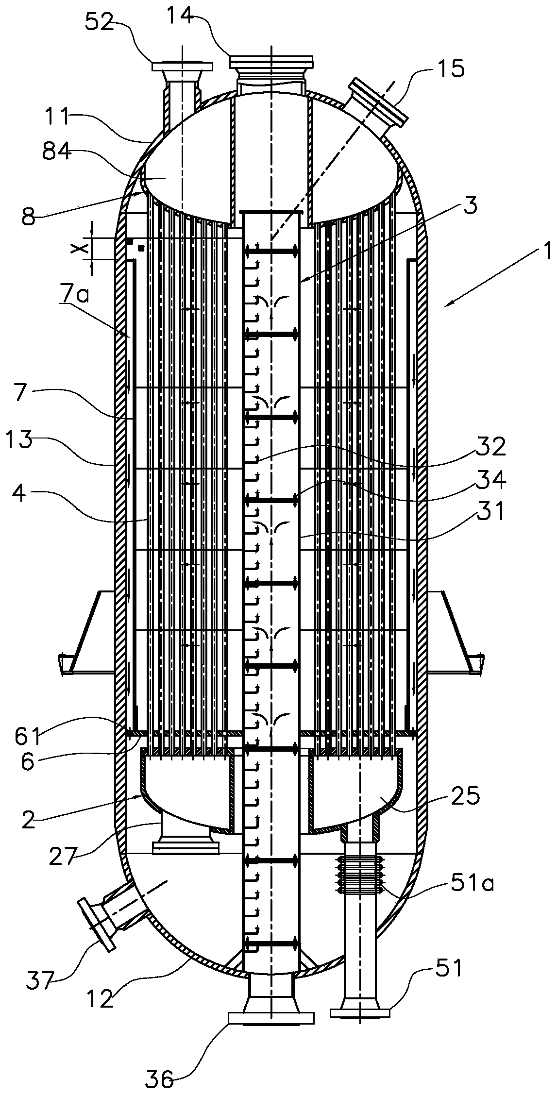
[0045] like Figure 1 to Figure 4 As shown, the new radial bed isothermal conversion reaction device includes: upper head 11, lower head 12, cylinder body 13, furnace body 1, floating tube box 2, lower tube plate 6, heat exchange tube 4, gas distributor 7. Raw material gas distribution pipe 3, upper tube plate 8 and other main components. Both the upper tube plate and the lower tube plate are horizontally arranged in the furnace body, and the inner chamber of the furnace body is divided into an upper chamber, a reaction chamber and a lower chamber sequentially from top to bottom.

[0046] The furnace body 1 is composed of an upper sealing head 11 , a lower sealing head 12 and a cylinder body 13 connected between the upper sealing head 11 and the lower sealing head 12 . The center of the upper head 11 is provided with a second manhole 14, and the second manhole 14 is buckled and covered with a manhole cover. The lower head 12 is provided with a feed gas inlet 36 and a shift g...

Embodiment 2

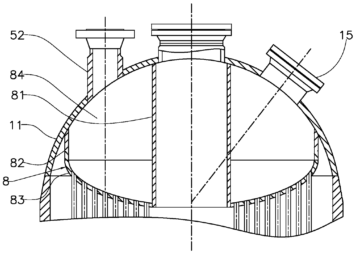
[0067] like Figure 5 As shown, the upper tube plate 8' of this embodiment adopts an annular tube plate 83' structure, and the middle part of the annular tube plate has a through hole. The periphery of the annular tube sheet is connected to the upper head 11 or the cylinder body 13, the periphery of the through hole is connected to the maintenance pipeline 81, and the upper edge of the maintenance pipeline 81 and the connecting cylinder joint are all connected to the upper head. The upper head 11, the upper tube sheet 8' and the overhaul pipeline 81 are assembled and welded to form an upper cavity 84. The maintenance pipeline 81 and the cylinder body 13 are concentric circular structures arranged concentrically. The outer diameter of the maintenance pipeline 81 is consistent with the diameter of the opening in the middle of the annular tube plate 83, and its size is determined according to the size of the raw gas distribution pipe 3. The upper head is provided with a steam d...


PUM


Abstract

The invention relates to a radial bed isothermal shift reaction device which comprises a furnace body, heat exchange pipes and a feed gas distribution pipe; the heat exchange pipes are vertically arranged, and the upper ends and the lower ends of the heat exchange pipes are connected to an upper tube plate and a lower tube plate which are transversely arranged in the furnace body respectively; aninner cavity of the furnace body is divided into an upper cavity, a reaction cavity and a lower cavity successively from top to bottom by the upper tube plate and the lower tube plate; an upper port of each heat exchange pipe is communicated with the upper cavity, and a lower port of each heat exchange pipe is communicated with the inner cavity of a floating tube box; the floating tube box is accommodated in the lower cavity, is hung above the heat exchange pipes and is not directly connected with the furnace body; an inlet of the floating tube box is communicated with an external boiler watersource, and an outlet of the upper cavity is communicated with external steam recovery equipment; a shift gas outlet is formed in the furnace body, and a gas distributor communicated with the shift gas outlet and an reaction area is arranged in the reaction cavity.

Description

technical field [0001] The invention relates to a reactor, in particular to a radial bed isothermal transformation reaction device. Background technique [0002] During the design process of the high-concentration CO shift process produced by pulverized coal gasification in China, adiabatic shift furnaces are often used in shift furnaces. Since the CO content in the crude synthesis gas is high, and the shift reaction is a strong exothermic process, the shift unit adopts multiple adiabatic furnaces in series to remove the reaction heat between the furnaces. This has also caused a series of problems such as the traditional high-concentration CO shift process is complicated, the number of shift furnaces is large, the system pressure drop is large, the equipment investment is high, and the temperature control of the shift furnace is difficult. [0003] The working principle of the isothermal shift furnace is relatively simple. Heat exchange pipes are built into the isothermal s...

Claims


Application Information

Patent Timeline
Patent Type & Authority Applications(China)
IPC IPC(8): B01J8/02C01B3/16C10K3/04
CPCB01J8/02B01J8/0285B01J2208/00132C01B3/16C10K3/04
Inventor 郭文元许仁春徐洁相红霞石翔鞠剑代小波
Owner CHINA PETROLEUM & CHEM CORP
Why Eureka
Try Eureka