Electrophoresis display assembly, electrophoresis displayer and preparation method of the same

An electrophoretic display, electrophoretic display technology, applied in the direction of instruments, nonlinear optics, optics, etc., can solve the problems of the effective display area of ​​the electrophoretic display, the difficulty of large-scale production and application, etc., to avoid excessive thickness of the photoelectric medium and avoid coating Difficulty, the effect of increasing the effective display area

Active Publication Date: 2013-05-08
GUANGZHOU OED TECH INC
View PDF15 Cites 35 Cited by
  • Summary
  • Abstract
  • Description
  • Claims
  • Application Information

AI Technical Summary

Problems solved by technology

Although researchers can coat microcapsules into a single layer by carefully controlling the coating speed in the implementation room, it is quite difficult for large-scale production applications
What's worse is that it is necessary to control the specific positions of these "caves" so that the "caves" can just fill the gaps between adjacent "caves" when deformed, so as to improve the effective display ratio of the electrophoretic display. It is difficult for those skilled in the art to realize
Therefore, if image 3 As shown, the single-layer microcapsule arrangement structure inevitably has a large number of gaps between the microcapsules, which may cause the actual effective display area of ​​the electrophoretic display to decrease.

Method used


Image

  • Electrophoresis display assembly, electrophoresis displayer and preparation method of the same
  • Electrophoresis display assembly, electrophoresis displayer and preparation method of the same
  • Electrophoresis display assembly, electrophoresis displayer and preparation method of the same

Examples


Embodiment 1

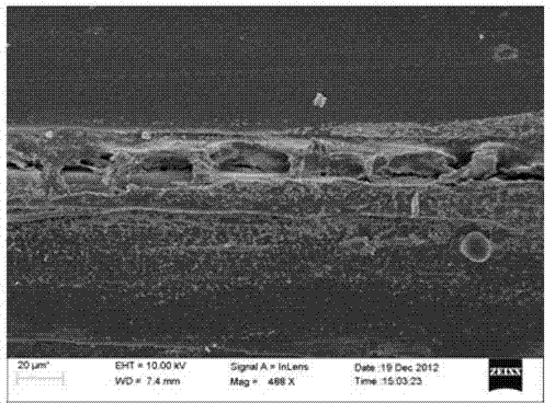
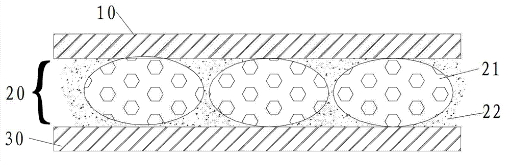
[0054] Figure 4 Shown is a schematic cross-sectional view of an electrophoretic display component. image 3 The electrophoretic display assembly in includes a transparent first electrode 10 and a photoelectric medium 20 attached to the side of the first electrode 10 . The photoelectric medium 20 has microcapsules 21 and an adhesive 22 , and the microcapsules 21 are fixed and adhered to the first electrode 10 through the adhesive 22 . Among them, the first electrode 10 is preferably made of indium oxide (ITO), SnO 2 , or ZnO / Al transparent conductive film implementation.

[0055] from Figure 4 It can be seen that the microcapsule 21 is in a flat shape with an aspect ratio greater than 1.2. Due to the varying degrees of deformation of the microcapsules 21, microcapsules 21 with an aspect ratio greater than 1.5 or greater than 1.75 may also appear. Although some microcapsules have small particle sizes or are deformed into elongated structures to fill the gaps between other...

Embodiment 2

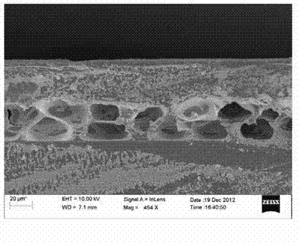
[0075] Figure 5 Shown is the electrophoretic display manufactured by using the electrophoretic display component with the structure in embodiment 1, the electrophoretic display component discussed in embodiment 1 and the second electrode 30, the second electrode 30 is arranged on the side adjacent to the photoelectric medium 20 and opposite to the first electrode 10 . In this embodiment, the second electrode 30 is disposed on the upper surface of a substrate, and the display component is fixed on the upper surface of the substrate by an adhesive 22 or a lamination operation. For the second electrode 30 and the substrate, a thin film transistor having a switching function and capable of applying an electric field is preferably used.

[0076] Image Quality Inspection

[0077] The researchers made the electrophoretic display components of the experimental group 1-4 according to the method in Example 2 and powered on the electrophoretic display so that the first electrode 10 an...


PUM

PropertyMeasurementUnit
particle diameteraaaaaaaaaa
thicknessaaaaaaaaaa
diameteraaaaaaaaaa

Abstract

The invention belongs to the field of electrophoresis display and particularly relates to an electrophoresis display assembly. The electrophoresis display assembly comprises a transparent first electrode and photoelectricity media attached to the lateral side of the first electrode, wherein the photoelectricity media are provided with microcapsule and adhesives, the microcapsule is scattered in the adhesives and is fixed by the adhesives. The microcapsule is accommodated with suspension liquid and a plurality of types of granules in the suspension liquid, a plurality of each type of granules are provided, at least one kind of granules can be diffused under the influence of an electric field, and the microcapsule in the photoelectricity media is generally distributed in a double-layer structure. A distribution structure of double-layer microcapsule not only avoids the defects that a prior single-layer microcapsule is difficult to coat, low in good product rate, bad in photoelectricity performance and the like, but also improves effective display area of an electrophoresis displayer.

Description

technical field [0001] The invention relates to a display assembly and a display, in particular an electrophoretic display, as well as a method and an assembly for producing such a display. Background technique [0002] An electrophoretic display refers to a display that uses the action of an electric field to cause multiple charged particles to migrate in a suspension to change the optical state of its viewing surface. Compared with liquid crystal displays, such displays are favored by people for their satisfactory brightness, high contrast ratio, wide viewing angle, bi-stability, and low power consumption, and have achieved considerable development through years of continuous research work. The above-mentioned "bistable state" has its well-known meaning in the art, and refers to a display state in which a display including a display element has at least one optical characteristic. [0003] However, through many years of research and application of electrophoretic displays...

Claims


Application Information

Patent Timeline
Patent Type & Authority Applications(China)
IPC IPC(8): G02F1/167
Inventor 苏晶刘祖良
Owner GUANGZHOU OED TECH INC
Why Eureka
Try Eureka