
Hollow annular traveling wave ultrasonic motor

An ultrasonic motor, hollow technology, applied in the direction of generator/motor, piezoelectric effect/electrostrictive or magnetostrictive motor, electrical components, etc., can solve the problems of space occupation, application limitation of ring traveling wave ultrasonic motor, etc. To achieve the effect of simple and compact structure

Inactive Publication Date: 2013-05-08
SOUTHEAST UNIV
View PDF4 Cites 29 Cited by
  • Summary
  • Abstract
  • Description
  • Claims
  • Application Information

AI Technical Summary

Problems solved by technology

The driving force of the ring-shaped traveling-wave ultrasonic motor is on the ring, and the space inside the ring is occupied by the rotating shaft and the support plate, which limits the application of the ring-shaped traveling-wave ultrasonic motor in fields such as rotating platforms that require a hollow structure.

Method used


Image

  • Hollow annular traveling wave ultrasonic motor
  • Hollow annular traveling wave ultrasonic motor
  • Hollow annular traveling wave ultrasonic motor

Examples


Embodiment Construction

[0022] The present invention can be better understood from the following examples. However, those skilled in the art can easily understand that the content described in the embodiments is only for illustrating the present invention, and should not and will not limit the present invention described in the claims.

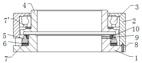
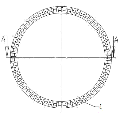
[0023] see figure 1 , figure 2 , image 3 with Figure 4 As shown, the hollow annular traveling wave ultrasonic motor of the present invention includes a base 1, a housing 2, a rotor 4, a stator 5 and piezoelectric ceramic sheets 6, and the base 1, housing 2, rotor 4 and stator 5 are all hollow ring structures. The stator 5 is arranged on the outside of the base 1 , and a piezoelectric ceramic sheet 6 is pasted on the bottom of the stator 5 . A first elastic washer 7 is also included, and the first elastic washer 7 is arranged on the bottom of the piezoelectric ceramic sheet 6 . The first elastic gasket 7 plays the role of assisting the adjustment of the pre-pr...


PUM


Abstract

The invention discloses a hollow annular traveling wave ultrasonic motor which comprises a base, an outer shell, a rotor, a stator and a piezoelectric ceramic piece, wherein the base, the outer shell, the rotor and the stator are all in a hollow annular structure, the stator is arranged on the outer side of the base, the piezoelectric ceramic piece is adhered to the bottom of the stator, the rotor is arranged on the stator, the bottom of the outer shell is connected with the bottom of the base, and the rotor rotates relative to the outer shell. According to the hollow annular traveling wave ultrasonic motor, a rotating shaft is not needed to output torque, the structure is simple and compact, and hollow parts can be fully utilized.

Description

technical field [0001] The invention belongs to the field of ultrasonic motor manufacturing and relates to a hollow ring traveling wave ultrasonic motor. Background technique [0002] The ultrasonic motor adopts a completely different driving principle from the traditional electromagnetic motor. It does not require the use of coils. The inverse piezoelectric effect of piezoelectric ceramics is used to excite the ultrasonic vibration of the stator, and the torque is output through the friction coupling between the stator and rotor. Therefore, compared with electromagnetic motors, ultrasonic motors have the advantages of fast dynamic response, low-speed high-torque, power-off self-locking, and good electromagnetic compatibility. They have broad application prospects in the fields of discontinuous motion, precision control, and intelligent robots. [0003] Ring traveling wave ultrasonic motor is the most widely used ultrasonic motor. The current ring-shaped traveling wave ultr...

Claims


Application Information

Patent Timeline
IPC IPC(8): H02N2/10H02N2/12
Inventor 胡敏强蒋春容金龙徐志科陆旦宏
Owner SOUTHEAST UNIV
Learn More