Feedback configuration method, device and system based on physics uplink sharing information channel
A technology of physical uplink sharing and channel sharing, which is applied in the direction of link quality-based transmission modification, transmission system, digital transmission system, etc., and can solve problems such as ensuring CSI accuracy and capacity
- Summary
- Abstract
- Description
- Claims
- Application Information
AI Technical Summary
Problems solved by technology
Method used
Image


Examples
Embodiment 1
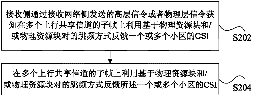
[0157] Assuming that UE1 is an R11 user, the network side configures a set of continuous subframes N (N ≥ 1) for UE1 through high-level signaling or a fixed method in the standard to indicate that UE1 has N consecutive subframes after a trigger Used to feed back the CSI of one or more nodes. When the network side needs UE1 to perform feedback on the PUSCH, the network side triggers UE1 to send information on n The CSI of one or more nodes is fed back on the +k (k≥4) subframe and subsequent N-1 consecutive subframes. UE1 obtains the continuous subframe number N (N≥1) of a set of PUSCH trigger feedback by receiving high-level signaling sent by the network side or configured in a fixed way in the standard, which is used to feed back one or more consecutive subframes after a trigger. Node's CSI. UE1 detects 1-bit signaling in the uplink and / or downlink control signaling in the physical downlink control channel sent by the network side on the nth (n≥0) subframe and triggers UE1 t...
Embodiment 2
[0159] Assuming that UE1 is an R11 user, the network side configures a set of continuous subframes N (N ≥ 1) for UE1 through high-level signaling or a fixed method in the standard to indicate that UE1 has N consecutive subframes after a trigger Used to feed back the CSI of one or more nodes. The 2-bit signaling in the uplink and / or downlink control signaling in the physical downlink control channel on the nth (n≥0) subframe on the network side triggers UE1 on and after n+k (k≥4) subframes The CSI of one or more nodes is fed back in consecutive N-1 subframes, wherein 1 bit of the 2 bits is used to indicate whether to trigger CSI feedback of the PUSCH, and 1 bit is used to indicate whether to frequency hop. UE1 obtains the continuous subframe number N (N≥1) of a set of PUSCH trigger feedback by receiving high-level signaling sent by the network side or configured in a fixed way in the standard, which is used to feed back one or more consecutive subframes after a trigger. Node's...
Embodiment 3
[0161]Assuming that UE1 is an R11 user, the network side configures UE1 a set of continuous subframe number N (N≥1) for PUSCH trigger feedback through high-level signaling or a fixed method in the standard to indicate UE1 After one trigger, N consecutive subframes are used to feed back the CSI of one or more nodes. M (M≥3) bit signaling in the uplink and / or downlink control signaling in the physical downlink control channel on the nth (n≥0) subframe on the network side triggers UE1 to operate at n+k (k≥4) The CSI of one or more nodes is fed back on the subframe and subsequent N-1 consecutive subframes, where 1 bit of the M bits is used to indicate whether to trigger the CSI feedback of the PUSCH, and the M-1 bit is used to indicate whether to frequency hop and / or Or the candidate frequency hopping pattern used for frequency hopping. UE1 obtains the continuous subframe number N (N≥1) of a set of PUSCH trigger feedback by receiving high-level signaling sent by the network side ...
PUM
 Abstract
Description
Claims
Application Information
 - R&D Engineer
- R&D Manager
- IP Professional
- Industry Leading Data Capabilities
- Powerful AI technology
- Patent DNA Extraction
Browse by: Latest US Patents, China's latest patents, Technical Efficacy Thesaurus, Application Domain, Technology Topic.
© 2024 PatSnap. All rights reserved.Legal|Privacy policy|Modern Slavery Act Transparency Statement|Sitemap