Eureka AIR delivers breakthrough ideas for toughest innovation challenges, trusted by R&D personnel around the world.

Bone conduction microphone

A technology of bone conduction microphone and condenser microphone, which is applied in the field of bone conduction microphone, can solve the problems such as inability to prevent noise, and achieve the effects of high sealing degree, clear sound and simple structure

Active Publication Date: 2013-05-08
BEIJING MILESTONE SCI & TECH DEV
View PDF9 Cites 8 Cited by
  • Summary
  • Abstract
  • Description
  • Claims
  • Application Information

AI Technical Summary

Problems solved by technology

But this structure does not prevent the noise transmitted by the shell

Method used


Image

  • Bone conduction microphone

Examples


Embodiment Construction

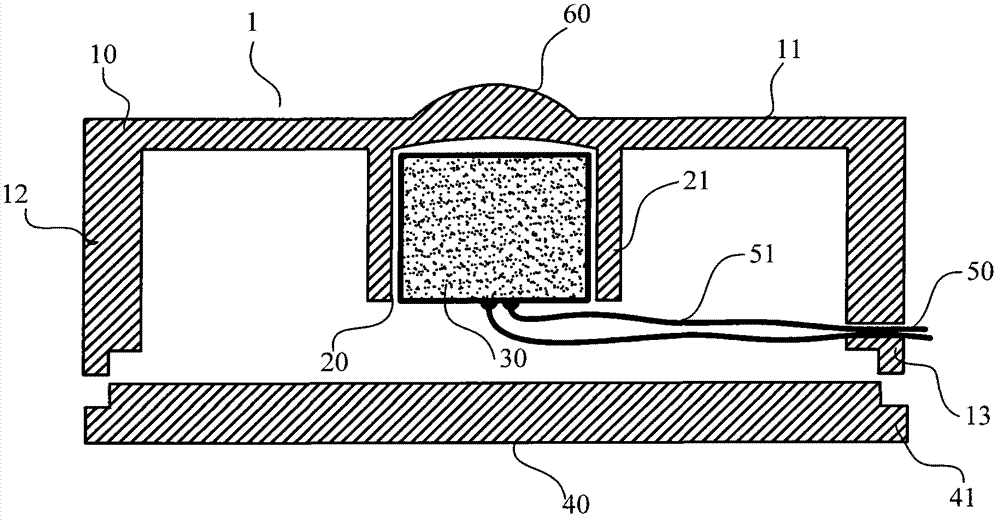
[0026] Refer below figure 1 Specific embodiments will be described in detail.

[0027] The bone conduction microphone of the present invention is applicable to any type of communication device capable of communicating over one or more public or private communication networks, e.g., cellular telephones, web-enabled cellular telephones, personal digital assistants (PDAs), handheld computers , Bluetooth wireless headsets, digital cameras, other types of portable computing and Internet access equipment and devices, etc. Due to the uncertainty of the use environment of this type of communication device, the microphone not only needs to have high sound clarity but also has the ability to shield various environmental noises.

[0028] figure 1 It is an exploded sectional view of a bone conduction microphone. The bone conduction microphone 1 includes a housing 10 , a pickup 20 and a cover 40 . The housing 10 is a cylindrical member with a bottom, and a connection boss 13 is formed o...


PUM


Abstract

The invention provides a bone conduction microphone. The bone conduction microphone comprises a shell, a seal cap connected with the shell, and a sound pick-up arranged in the shell. A connecting cylinder is arranged in the shell, and the sound pick-up is arranged in the connecting cylinder. With the structure, vibration on the shell can be prevented from entering into the sound pick-up through screening of the shell, noise can be avoided, and therefore sound articulation can be improved.

Description

technical field [0001] The invention relates to a bone conduction microphone. Background technique [0002] General microphones use air conduction and are open. Although they can obtain good sound quality, the biggest disadvantage is that they cannot isolate the external background sound source. When talking in a noisy environment, they cannot filter the ambient noise, causing inconvenience to the user. Compared with the microphone that uses air conduction for detection, the bone conduction microphone has stronger anti-noise ability because it is attached to the user's skull and detects the vibration of the skull when the user speaks through bone conduction. [0003] The Chinese patent with the authorized notification number CN2814852Y discloses a bone conduction microphone, wherein the microphone and the vibrating surface are connected to each other through a shell, and the vibrating surface and the shell are flexibly connected to form a bone conduction microphone between t...

Claims


Application Information

Patent Timeline
Patent Type & Authority Applications(China)
IPC IPC(8): H04R1/08H04R1/46
Inventor 修翔凤米旺蔡希昌
Owner BEIJING MILESTONE SCI & TECH DEV
Why Eureka
Eureka Blog
Learn More