

Vehicle seat and rigidity setting method of vehicle seat
A vehicle and seat technology, which is applied to vehicle seats, special positions of vehicles, movable seats, etc. It can solve the problems that the seated person cannot obtain, the sense of oppression increases, and the comfortable seating feeling etc.
- Summary
- Abstract
- Description
- Claims
- Application Information
AI Technical Summary
Problems solved by technology
Method used
Image

Examples
no. 1 Embodiment approach
[0049] refer to Figure 1 ~ Figure 3 A vehicle seat 1 for a rear seat according to a first embodiment of the present invention will be described.
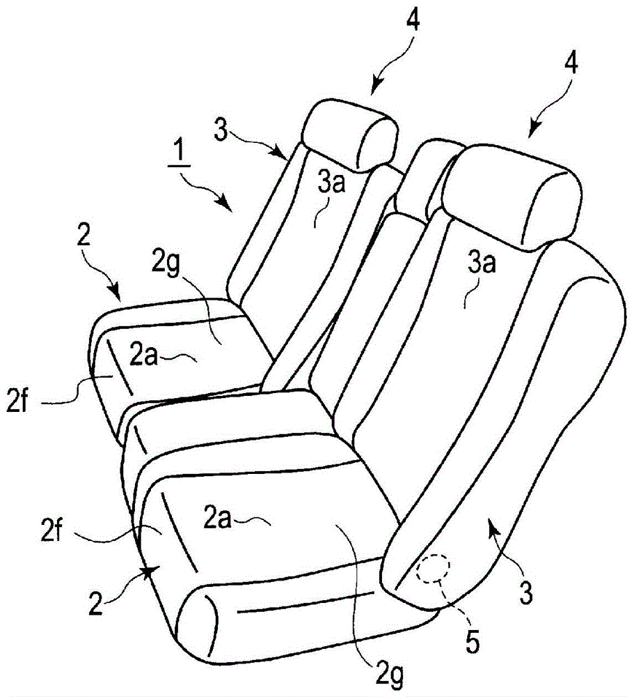
[0050] Such as figure 1 As shown, the vehicle seat 1 for a rear seat according to this embodiment mainly includes a seat cushion 2 and a seat back 3 . The seat back 3 is connected to the rear end portion of the seat cushion 2 so as to be tiltable in the front-back direction by a reclining device 5 . A headrest 4 is provided at an upper end portion of the seat back 3 .
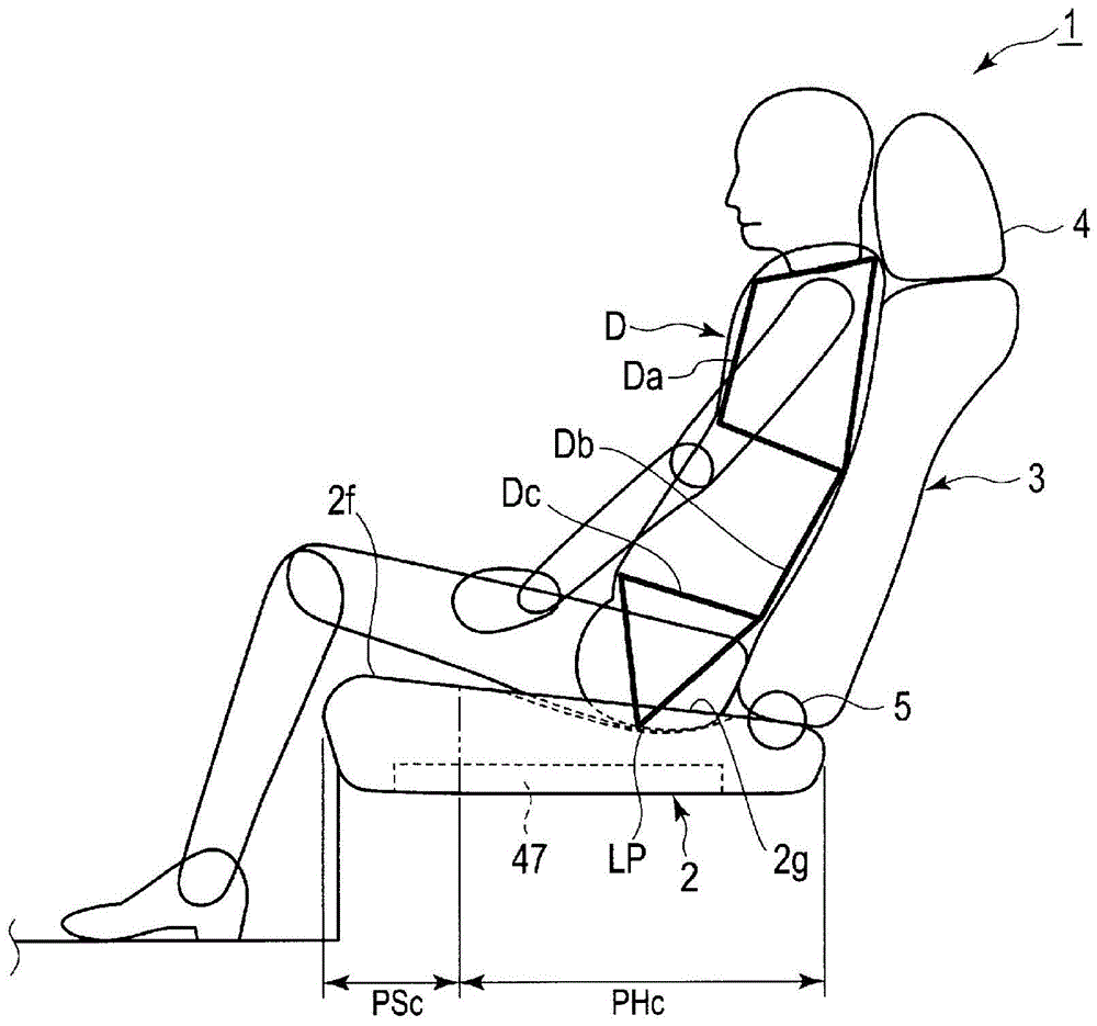
[0051] Such as figure 2 As shown, the seat cushion 2 has at least a front portion 2f and a rear portion 2g. The front portion 2f refers to a portion including the front end of the seat cushion 2, and refers to the length of the thigh (from the greater trochanter to the knee joint) from the front end of the seat cushion 2 to the thigh length of the seated person D in a side view of the seat cushion 2. length) about 1 / 6 to 1 / 3 of the range. On the other hand, t...
no. 2 Embodiment approach
[0080] refer to Figure 4 ~ Figure 8 A vehicle seat 1 for a rear seat according to a second embodiment of the present invention will be described. The present embodiment is an example in which the rigidity distribution described below is applied to the seat back 3 in the vehicle seat 1 of the first embodiment.
[0081] Such as Figure 4 and Figure 5 As shown, in the seat back 3 of this embodiment, the support reaction force fa of the seated person D is set at the central part in the vertical direction. 1Smaller low rigidity area PSb. Here, the support reaction force refers to the force that the occupant D receives from the surface that supports the occupant D (for example, the back surface 3 a ). The support reaction force can be determined based on, for example, the maximum amount of deformation (subsidence) of the support surface when a pressing surface of a predetermined shape and size is pressed against the support surface with a predetermined pressure. For example, ...
no. 3 Embodiment approach
[0166] refer to Figure 15 ~ Figure 16 A vehicle seat 1 for a rear seat according to a third embodiment of the present invention will be described. The present embodiment is an example in which the reaction force characteristics described below are applied to the front portion 2 f of the seat cushion 2 in the vehicle seat 1 of the first embodiment.
[0167] In this embodiment, if Figure 15As shown, the following reaction force characteristics are applied to the low-rigidity region PSc provided on the front portion 2f of the seat cushion 2: the support reaction force fb is large relative to the seating load acting from above, and the supporting reaction force fb is large compared to the seating load acting from the front. The seated load has a smaller support reaction force fc, that is, the support reaction force fb for the seated load acting from above is larger than the support reaction force fc for the seated load acting from the front (fb>fc). The seating load refers to ...
PUM
 Abstract
Description
Claims
Application Information