Low voltage rigid cable

A cable and rigid technology, applied in the field of rigid cable structure and lighting system, can solve the problems that rigid cables are not suitable for distributing current, and the application of rigid cables is limited.

Inactive Publication Date: 2013-05-08
TP24
View PDF7 Cites 4 Cited by
  • Summary
  • Abstract
  • Description
  • Claims
  • Application Information

AI Technical Summary

Problems solved by technology

Therefore, the application of this rigid cable is limited
For example, this rigid cable is not suitable for distributing current to electrical devices requiring mains AC voltage power

Method used


Image

  • Low voltage rigid cable
  • Low voltage rigid cable
  • Low voltage rigid cable

Examples


no. 1 example

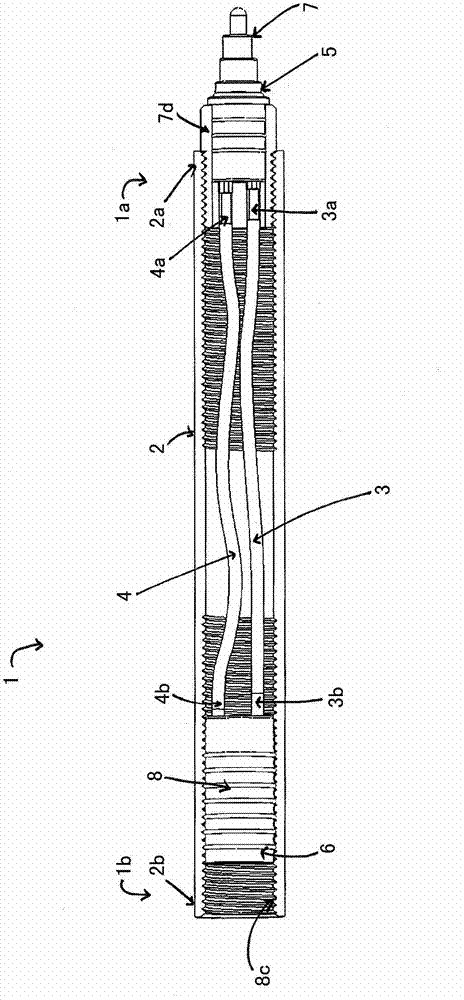
[0107] Figures 1a-1d A first embodiment relating to a rigid cable (1) comprising a releasable male connection means (5) arranged at a first end (1a) of the cable and a second end (1b) of the cable The releasable female connection device (6).

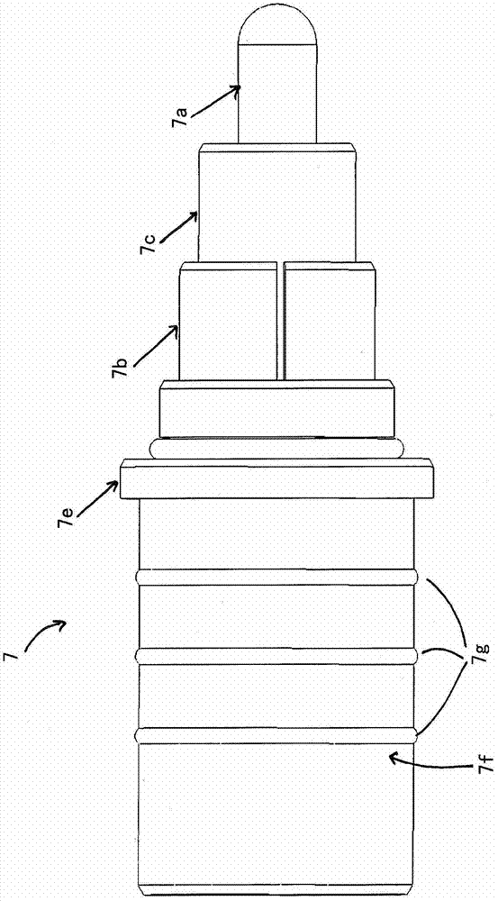
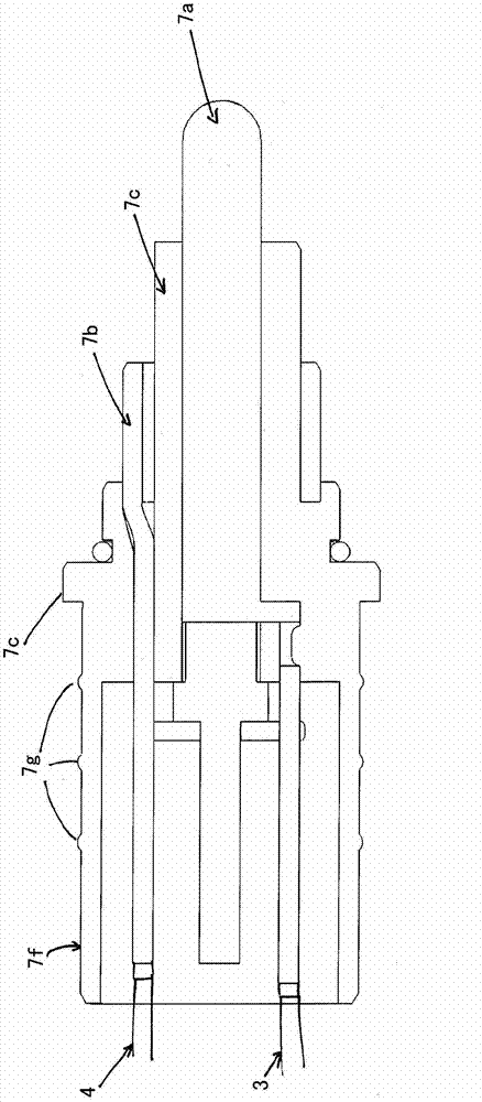
[0108] as Figures 1a-1d As shown, the male connection means of the rigid cable comprises a push-fit plug part (7) protruding from the first end (2a) of the housing of the rigid cable. The plug part comprises a live central pin contact (7a) (live contact) connected to the first end of the live conductor (3a) and an annular sleeve neutral contact connected to the first end of the neutral conductor (4a) (7b) (neutral contact). The central pin contact and the annular sleeve neutral contact are coaxially arranged in steps and separated by an insulating layer (7c). The plug portion also includes a ground contact (7d) connected to the first end (2a) of the housing. The ground contact is arranged coaxially in a step with respect to the ce...

no. 2 example

[0159] Figure 6a and 6b An embodiment of a lighting system suitable for ceiling mounting is shown. In this embodiment, the lighting system further includes a ceiling light box (C), a pole (S), a mounting unit (MU) and a plurality of lamp support arms (A).

[0160] The ceiling light box (C) is configured to be mechanically connected to the ceiling and electrically connected to the power grid.

[0161] The rod S is configured to be mechanically and electrically connected to the ceiling light box and the mounting unit. The rod is configured to extend downwardly from the ceiling light box. The first end of the rod is configured to be mechanically and electrically connected to the ceiling light box. The second end of the rod is configured to be mechanically and electrically connected to the mounting unit. It can be seen that in Figure 6b In, the rod is configured to be detachably connected to the ceiling light box and the mounting unit. The rod comprises two rigid cables (...


PUM


Abstract

A first aspect of the invention relates to a low voltage rigid cable comprising a substantially rigid housing, a live conductor arranged within the housing, a neutral conductor arranged within the housing, a first coupling means to couple the rigid cable with a first member, a second coupling means configured to couple the rigid cable with a second member and protection means to protect against electric shock. The protection means may comprise an earth conductor and insulating means configured to form an insulating barrier between the conductive parts of the rigid cable. In an embodiment of the invention, the housing may be configured to form an earth conductor. Further aspects of the invention relate to a rigid cable structure.

Description

technical field [0001] The present disclosure relates to rigid cables with low voltage ratings. The present disclosure also relates to rigid cable structures comprising at least one rigid cable. Furthermore, the invention relates to a lighting system comprising one or more rigid cables. Background technique [0002] A rigid cable is understood as a cable having a substantially rigid structure. Due to its rigid structure, rigid cables are able to substantially retain their shape under applied loads. For this reason, rigid cables have been used to support and transmit electrical current to electrical devices. [0003] UK patent application 89076739.1 describes a lighting system comprising one or more rigid cables. The configuration of the lighting system can be changed by adding or removing rigid cables. The rigid cable includes an inner live conductor, an outer neutral conductor and connecting means for securing the rigid cable end-to-end with other cables of substantial...

Claims


Application Information

Patent Timeline
Patent Type & Authority Applications(China)
IPC IPC(8): F21V21/12H01B7/00H01B7/16H01B13/004H01R25/14
CPCH02G15/00F21V21/002F21V21/10F21V21/12H01R24/38F21V23/06F21V21/02H01R2103/00H01B13/004H01R25/003F21S8/065F21Y2101/02F21S2/005F21Y2115/10H01B7/16
Inventor 肖恩·戴维斯
Owner TP24
Why Eureka
Try Eureka