Bending device for glass legs

A technology of temples and equipment, applied in the field of semi-automatic equipment, can solve the problems of uneven springback of temples, achieve consistent curvature of temples, improve production efficiency and product quality, and completely consistent bending conditions

Inactive Publication Date: 2013-05-15
ZENNI OPTICAL
View PDF10 Cites 3 Cited by
  • Summary
  • Abstract
  • Description
  • Claims
  • Application Information

AI Technical Summary

Problems solved by technology

[0003] In order to overcome the problem of uneven springback of the mirror legs after bending, the object of the present invention is to provide a mirror leg bending equipment, which is provided with a sub-mold on the base, and the lower mold and the upper mold have the same curvature to fix the mirror. leg, and then use the forward and reverse motor to bend it to ensure the same curvature of the mirror legs

Method used


Image

  • Bending device for glass legs

Examples


Embodiment Construction

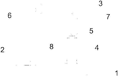
[0011] Depend on figure 1 It is known that a mirror leg bending device is composed of a base 1, a forward and reverse motor 2, a PLC controller 3, a sub-mold 4, a pressure gauge 5, a screw rod 6, a pressure rod 7 and a slot 8 for the sub-mold, The front end of the base 1 has grooves, which are used to fix the lower mold of the sub-mold 4, and the rear end is fixed with a forward and reverse motor 2 and a bracket. The inside of the bracket is provided with a screw rod 6 for controlling the up and down movement of the pressure rod 7, and the sub-mold 4 is installed on the pressure rod 7, the PLC controller 3 is connected with the forward and reverse motor 2 and the pressure gauge 5, and the forward and reverse motor 2 drives the screw rod 6 to rotate, so that the upper pressure rod 7 in the bracket passes through the PLC controller 3. Timing bending is performed on the mirror legs in the sub-mold 4 survey, and it will automatically return after forming. The lower mold of the su...


PUM


Abstract

A bending device for glass legs comprises a base seat 1, a positive-negative rotating motor 2, a programmable logic controller (PLC)3, a sub master pattern 4, a pressure gage 5, a lead screw 6 and a pressurized rod 7. The bending device for the glass legs is characterized in that the positive-negative rotating motor 2 drives the lead screw 6 to rotate, through the PLC 3the pressurized rod 7 on a support is enabled to bend the glass legs which is within a range prospected by the sub master pattern 4 in a fixed-time mode, and automatic reset is achieved after forming is carried out. According to the bending device for the glass legs, the problem that an error is generated when an ordinary moulding press is used for bending the glass legs in a manual mode is solved, bending degree of the glass legs is enabled to be accorded, semi-automatic control is used, and production efficiency and product quality are improved. The bending device for the glass legs can set pressure and time of bending, bending conditions are enabled to be completely identical, and the bending degree of the glass legs is identical.

Description

technical field [0001] The invention relates to a semi-automatic device for bending glasses legs. Background technique [0002] At present, the known mirror leg bending tools all use ordinary molding machines to manually bend the temples. The curvature control only depends on the experience of the mold or the operator. Due to uneven force, plastic and plate mirror legs The rebound after bending makes the difference in camber. Contents of the invention [0003] In order to overcome the problem of uneven springback of the mirror legs after bending, the object of the present invention is to provide a mirror leg bending equipment, which is provided with a sub-mold on the base, and the lower mold and the upper mold have the same curvature to fix the mirror. Legs, and then use the forward and reverse motor to bend them to ensure the same curvature of the mirror legs. [0004] The technical solution adopted by the present invention to solve the technical problem is: a mirror le...

Claims


Application Information

Patent Timeline
Patent Type & Authority Applications(China)
IPC IPC(8): B21D11/00
Inventor 赵琳
Owner ZENNI OPTICAL
Why Eureka
Try Eureka