
Automatic-control flag lifting device

A technology for lifting devices and flags, applied in the direction of lifting devices, building types, buildings, etc., can solve the problems of cumbersome, technical lag, and the flag is not flying smoothly, and achieves the goal of overcoming cumbersome delays, overcoming poor technology, and promoting the use of social economy. obvious effect

Inactive Publication Date: 2013-05-15
LIUZHOU JINGYANG ENERGY SAVING TECH RES DEV
View PDF5 Cites 1 Cited by
  • Summary
  • Abstract
  • Description
  • Claims
  • Application Information

AI Technical Summary

Problems solved by technology

[0002] So far, the raising and lowering of various flags on various solemn occasions mostly adopts manual operation and general electric control operation, and the lifting settings are simple, the technology lags behind and the operation is inconvenient. When it is windy, the flag cannot fly smoothly because of being wet and blowing due to insufficient wind power. People need to improve it urgently.

Method used


Image

  • Automatic-control flag lifting device
  • Automatic-control flag lifting device

Examples


Embodiment Construction

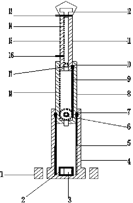
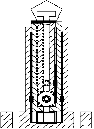
[0018] As shown in the figure, the self-control flag lifting device of the present invention includes two parts: an outer device and an inner device.

[0019] The external device includes a fixed base 1, a lower pole 4, a middle pole 8, an upper pole 11, an air blower 12, an upper pull ring 13, a blast hole 15 and a pull ring 16;

[0020] The periphery of the fixed base 1 is provided with a fixing hole and the upper side is connected with the lower end of the lower pole 4, and its function is to fix the connection with the ground through the screw and fix the lower pole 4 and set the automatic controller 2 and the storage battery 3;

[0021] The lower end of the lower support rod 4 is connected to the upper side of the fixing seat 1 and the inner side is socketed with the outer side of the middle support rod 8, and the two sides of the inner wall are symmetrically attached with sliding grooves 5, and its function is to support the middle support rod 8 to move up and down in a l...


PUM


Abstract

The invention discloses an automatic-control flag lifting device. the automatic-control flag lifting device comprises an automatic controller, a storage battery, a lower chute, a lower gear, a sliding clamp, a middle chute, an upper sliding clamp, an upper gear groove, an upper gear, a middle gear groove, a fixing seat, a lower radius rod, a middle radius rod, an upper radius rod, a blower, an upper pull-tab, a blowing hole and a lower pull-tab, wherein the automatic controller and the storage battery is arranged in the inner side of the fixing seat. The lower chute is arranged at the inner side wall of the lower radius rod. The lower gear is arranged on the inner side of the middle radius rod. The middle sliding clamp is arranged at the lower end of the middle radius rod. The middle chute is arranged on the inner side of the middle radius rod. The upper sliding clamp is arranged on the lower side of the upper radius rod. The upper gear groove is arranged on the inner side of the upper radius rod. The upper gear is arranged on the inner side of the upper radius rod. The middle gear groove is arranged on the inner side of the middle radius rod. The fixing seat is connected with the lower radius rod. The lower radius rod is connected with the upper portion of the fixing seat, and the inner side of the fixing seat is sleeved with the outer side of the middle radius rod. The middle radius rod is sleeved in the lower radius rod. The upper radius rod is sleeved in the middle radius rod. The blower is sleeved with the upper radius rod. The upper pull-tab and the lower pull-tab are arranged at one side of the upper radius rod in a parallel mode, and the blowing hole is formed between the upper radius rod and the upper pull-tab.

Description

technical field [0001] The invention relates to a device, in particular to a self-controlled flag raising and lowering device. Background technique [0002] So far, the raising and lowering of various flags on various solemn occasions mostly adopts manual operation and general electric control operation, and the lifting settings are simple, the technology lags behind and the operation is inconvenient. During the windy weather, the flag can't float because of being drenched and blows and flutters smoothly because of insufficient wind power, so people need to improve and improve urgently. For this reason, be necessary to invent a kind of comprehensive technology content high, can carry out timing automatic control and remote control and speed regulation lifting, and more practical and flag-raising ceremony seem more high-grade solemn and sacred self-control flag lifting device. Contents of the invention [0003] The purpose of the present invention is to solve the problem o...

Claims


Application Information

Patent Timeline
IPC IPC(8): E04H12/32B66F11/00
Inventor 韦战
Owner LIUZHOU JINGYANG ENERGY SAVING TECH RES DEV
Learn More