Supercharge Your Innovation With Domain-Expert AI Agents!

A temperature relay life tester

A technology of temperature relay and tester, applied in circuit breaker test and other directions, can solve the problems of large manual recording error and low test accuracy, and achieve the effect of high test accuracy

Inactive Publication Date: 2015-09-30
中国电子科技集团公司第四十研究所
View PDF6 Cites 0 Cited by
  • Summary
  • Abstract
  • Description
  • Claims
  • Application Information

AI Technical Summary

Problems solved by technology

At present, the life test of temperature relays has been using the method of temporarily building test lines and manually recording the number of times. This method has the problems of low test accuracy and large manual recording errors.

Method used


Image

  • A temperature relay life tester

Examples


Embodiment Construction

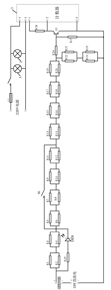
[0011] A life tester for a temperature relay, comprising a resistance load circuit with one end connected to the positive pole of the temperature relay, and the other end connected to the input end of a counter 3 through a sampling drive circuit. The resistance load circuit includes resistors R1 to R24, resistors R1 and R2 connected in parallel, resistors R3 and R4 connected in parallel, resistors R5 and R6 connected in parallel, resistors R7 and R8 connected in parallel, resistors R9 and R10 connected in parallel, resistors R11 and R12 connected in parallel, and resistor R13 , R14 in parallel, resistors R15, R16 in parallel, resistors R17, R18 in parallel, resistors R19, R20 in parallel, resistors R21, R22 in parallel, resistors R23, R24 in parallel, the above two parallel terminals are connected in series, and the other of the resistors R1, R2 A parallel terminal is connected to the positive pole of the temperature relay; the sampling drive circuit includes a resistor R26, on...


PUM


Abstract

The invention relates to a testing device of temperature relay service life. The testing device of temperature relay service life comprises a resistive load circuit, one end of the resistive load circuit is connected with a positive electrode of a temperature relay, and the other end of the temperature relay is connected with an input end of a counting device through a sampling drive circuit. When the temperature relay operates pick-up, a light-emitting diode (LED) 1 is turned on, and the counting device displays '1'. When the temperature relay opens, the LED is turned off. The temperature relay picks up again, the LED is turned on, the counting device displays '2', the temperature relay opens, and the LED is turned off. The temperature relay picks up and opens repeatedly, and the counting device accumulates counts. The testing device of the temperature relay service life is capable of automatically loading rated load currents, recording and indicating operation times of the temperature relay, and conducting excess load detections and operation times recording. No manual test is needed, and the test accuracy is high.

Description

technical field [0001] The invention relates to the field of automatic control, in particular to a temperature relay life tester. Background technique [0002] The life test of the temperature relay is to load the rated load current to the temperature relay and record the number of actions indicating the temperature relay. At present, the life test of temperature relays has been using the method of temporarily building test lines and manually recording the number of times. This method has the problems of low test accuracy and large manual recording errors. Contents of the invention [0003] The purpose of the present invention is to provide a temperature relay life tester which can automatically test the life of the temperature relay and has high testing accuracy. [0004] In order to achieve the above object, the present invention adopts the following technical solutions: a temperature relay life tester, comprising a resistance load circuit connected to the positive pole...

Claims


Application Information

Patent Timeline
Patent Type & Authority Patents(China)
IPC IPC(8): G01R31/327
Inventor 刘秀梅刘超李为国王小虎华海月
Owner 中国电子科技集团公司第四十研究所
Features
  • R&D
  • Intellectual Property
  • Life Sciences
  • Materials
  • Tech Scout
  • Unparalleled Data Quality
  • Higher Quality Content
  • 60% Fewer Hallucinations
Learn More