Method for generating a signal for measuring distance, and method and system for measuring distance between a sender and a receiver

A distance measurement, transmitter technology, applied in the field of generating signals for distance measurement and for distance measurement and system between transmitter and receiver, which can solve problems such as difficulty in using short pulses

Inactive Publication Date: 2013-05-15
FRAUNHOFER GESELLSCHAFT ZUR FOERDERUNG DER ANGEWANDTEN FORSCHUNG EV
View PDF5 Cites 2 Cited by
  • Summary
  • Abstract
  • Description
  • Claims
  • Application Information

AI Technical Summary

Problems solved by technology

[0003] However, the fundamental problem with this approach is that it may be difficult to take advantage of short pulses, since the length of the impulse response in the channel determines when the next pulse can be transmitted and thus the maximum pulse rate

Method used


Image

  • Method for generating a signal for measuring distance, and method and system for measuring distance between a sender and a receiver
  • Method for generating a signal for measuring distance, and method and system for measuring distance between a sender and a receiver
  • Method for generating a signal for measuring distance, and method and system for measuring distance between a sender and a receiver

Examples


Embodiment Construction

[0031] Before discussing the present invention in detail with reference to the drawings, it should be noted that in the following embodiments, identical or functionally equivalent elements have the same reference numerals. Thus, descriptions of elements with the same reference numerals can be mutually interchanged and / or used in different embodiments.

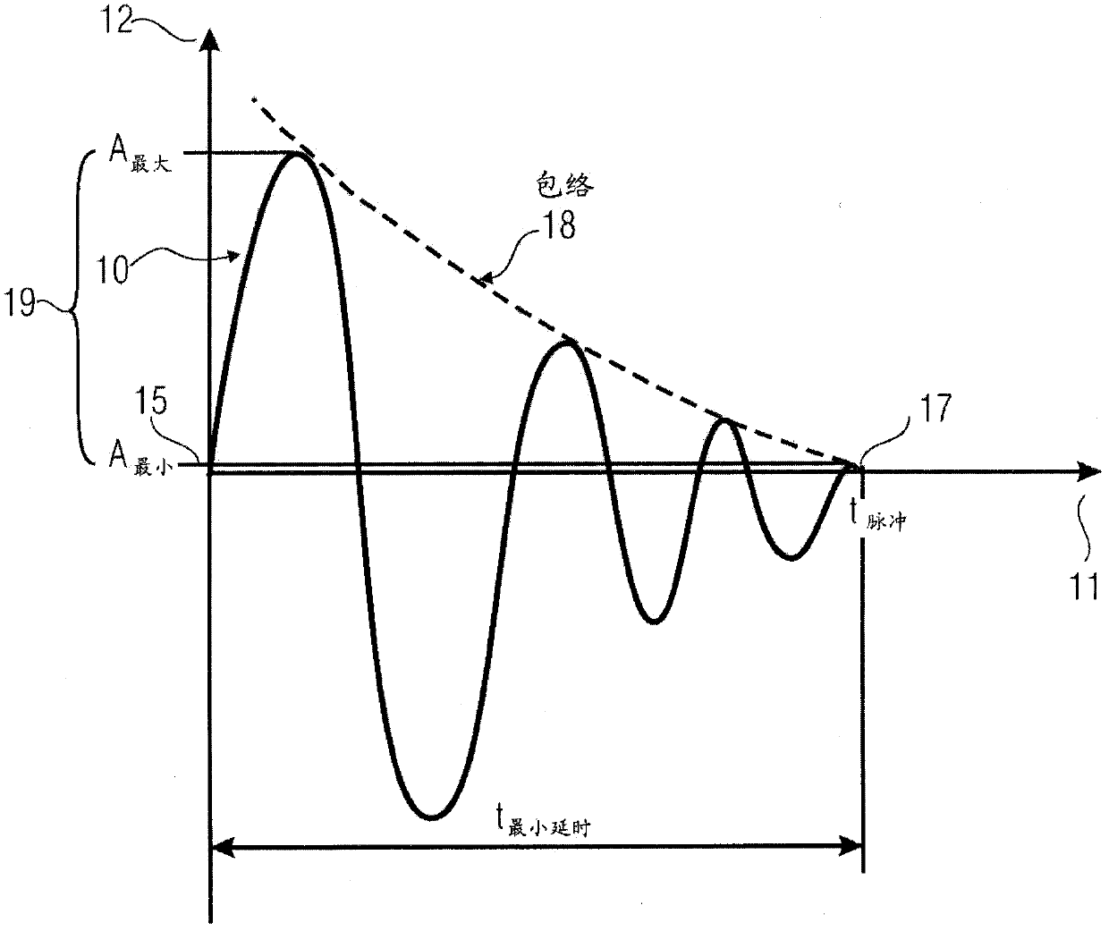
[0032] Figure 1 shows an exemplary diagram of a pulse 10 of the present invention. The pulse 10 shown in Fig. 1 may be, for example, a bandwidth-limited UWB pulse. In particular, in an embodiment, the pulse 10 of the present invention may be a single pulse in a train of pulses, wherein the train may be transmitted from a transmitter as a burst-like signal. In FIG. 1 , time is plotted on the horizontal axis 11 and the amplitude of the signal or pulse is plotted on the vertical axis 12 . As shown in Figure 1, the length t is defined by the time from the start 15 to point 17 of the pulse 脉冲 , whose envelope 18 has decayed to a ...


PUM


Abstract

The aim of the invention is to generate a signal for measuring distance between a sender and receiver. This is achieved in that a sequence of pulses is generated with specified time intervals between individual pulses of the sequence, said time intervals being different each time.

Description

technical field [0001] Embodiments of the invention relate to a method of generating a signal for distance measurement between a transmitter and a receiver. A further embodiment of the invention relates to an idea for distance measurement between a transmitter and a receiver. Finally, a further embodiment of the invention relates to a method of reducing signal superposition due to reflections in an ultra-wideband system for positioning. Background technique [0002] The technical literature presents different methods of time-shifting UWB (Ultra Wideband) pulses to encode information into the signal. A process known in the prior art is PPM (Pulse Position Modulation). Therefore, the repetition rate of the pulses is implemented such that the channel must be attenuated by the next pulse so that reflections of previous pulses and superposition of pulses do not occur in the receiver. In communication engineering, this is called intersymbol interference. [0003] However, the ...

Claims


Application Information

Patent Timeline
Patent Type & Authority Applications(China)
IPC IPC(8): G01S11/00
CPCG06F15/00G01B21/16G01S11/02
Inventor 赖纳·雷特科瓦斯基安德烈·艾德洛特
Owner FRAUNHOFER GESELLSCHAFT ZUR FOERDERUNG DER ANGEWANDTEN FORSCHUNG EV
Why Eureka
Try Eureka