
Crosswind Compensation Method for Electric Steering Based on Image Sensor for Lane Keeping Assist System

An image sensor and auxiliary system technology, applied in the field of vehicle systems, can solve the driver's steering fatigue, compensation and other problems, and achieve the effects of relieving steering fatigue, improving efficiency, and shortening monitoring time.

Active Publication Date: 2017-08-01
HYUNDAI MOBIS CO LTD
View PDF6 Cites 0 Cited by
  • Summary
  • Abstract
  • Description
  • Claims
  • Application Information

AI Technical Summary

Problems solved by technology

However, the technology in this patent only considers the driving characteristics of the driver, such as Figure 1-A The vehicle is stressed by a side wind, as shown, or as Figure 1-B As shown, when the vehicle is driving on a sloping road surface, that is, when external factors have an effect on the driver's straight travel, this technical solution cannot compensate for the situation
Therefore, in the prior art scheme, in order to keep going straight, the driver needs to directly compensate for the external force, so he must apply a steering force in the direction opposite to the external force. Constantly exerting force, which causes the driver to experience steering fatigue

Method used


Image

  • Crosswind Compensation Method for Electric Steering Based on Image Sensor for Lane Keeping Assist System
  • Crosswind Compensation Method for Electric Steering Based on Image Sensor for Lane Keeping Assist System
  • Crosswind Compensation Method for Electric Steering Based on Image Sensor for Lane Keeping Assist System

Examples


Embodiment Construction

[0015] The present invention will be described below in conjunction with the accompanying drawings and embodiments, which will make more forms of the above and the present invention clearer.

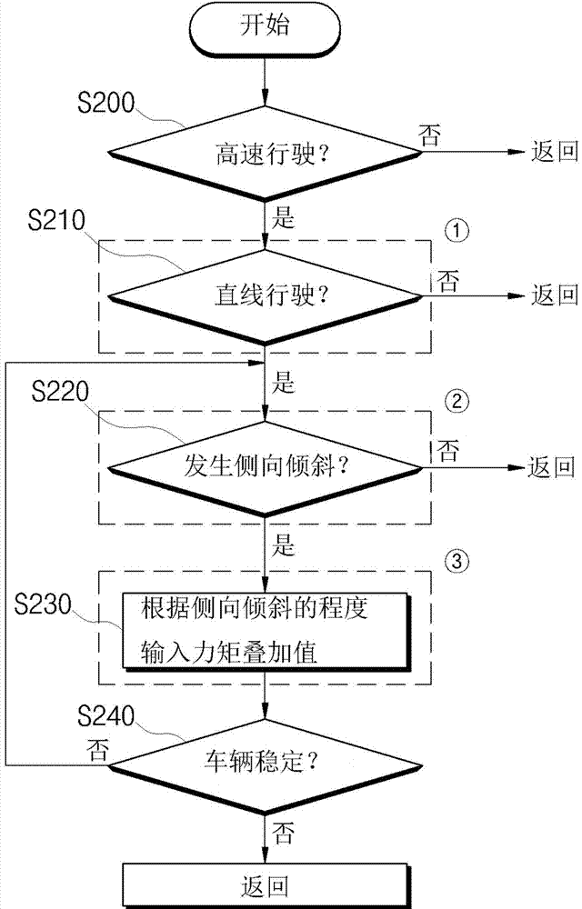
[0016] Such as figure 2 As shown, it is a basic flowchart of crosswind compensation performed by the MDPS (Motor-Driven Power Steering) crosswind compensation system of the present invention.

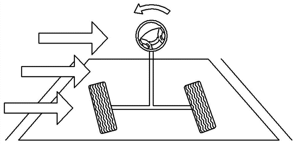
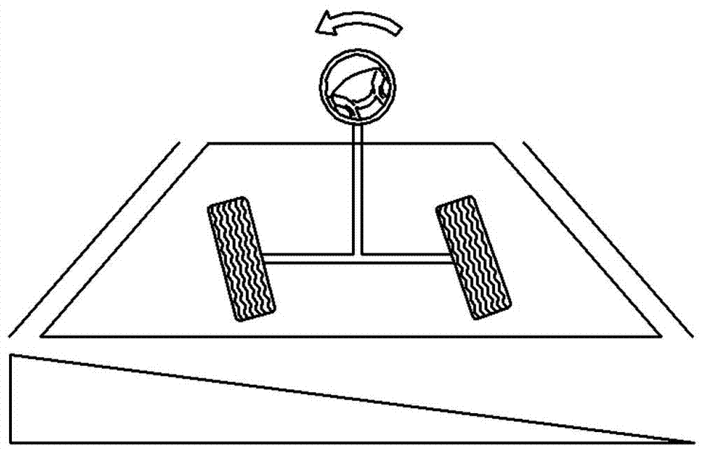
[0017] During the running of the vehicle, the control unit first determines whether the vehicle is running at high speed in order to perform steering control of the crosswind compensation system (step S200). For example, the control unit judges that the vehicle is traveling at a high speed when the vehicle is traveling at a speed above 60kph. If it is determined that the vehicle is in a high-speed driving state, the control unit determines whether the vehicle is in a straight-going state (step S210). If it is determined that the vehicle is in a straight-ahead state, the control unit determines ...


PUM


Abstract

The invention proposes an electric steering crosswind compensation method based on an image sensor used in a lane keeping assist system. To perform crosswind compensation, it is first necessary to judge whether the vehicle is going straight. In addition to applying information related to steering angle and steering angular velocity, the present invention also obtains the curvature information of the road ahead from the image sensor of the lane keeping assist system, and the azimuth information and relative The lateral displacement information of the lane, and judge whether the vehicle is going straight according to the above information. In this way, after accurately and quickly judging whether the vehicle is going straight, the crosswind compensation is performed.

Description

technical field [0001] The invention relates to a vehicle system, in particular to the steering technology in the vehicle system, in particular to an electric steering crosswind compensation method based on an image sensor used in a lane keeping assist system. Background technique [0002] Korean Patent No. 10-2006-0069679 has made the technology related to the electric steering gear that reflects the driving characteristics of the driver a well-known technology. This kind of electric steering gear judges the frequency and magnitude of acceleration and deceleration by the root mean square value of the acceleration on the one hand, and judges the frequency and magnitude of the driver's emergency steering by the root mean square value of the steering angular velocity on the other hand. This operation function reflecting the driving characteristics can increase or decrease the steering assist power according to the driver's driving characteristics, thereby ensuring the stabilit...

Claims


Application Information

Patent Timeline
Patent Type & Authority Patents(China)
IPC IPC(8): B60W30/12B60W40/072B62D5/04
CPCB60W30/12B60W10/20B60W40/072B60W2510/205B60W2540/18B60W40/105B62D6/10B60W2552/30B60W2520/10B60W2510/202B60Y2300/12B60W2420/403
Inventor 金斗炯
Owner HYUNDAI MOBIS CO LTD
Learn More