Multifunctional rail measuring system and method thereof

A measurement system and multi-functional technology, which is applied in the directions of measuring device, measuring inclination, surveying and navigation, etc., can solve the problems of lack of scanning measurement of rail surface contour and low accuracy of track direction measurement

Active Publication Date: 2013-05-22
API ZC PRECISION INSTUMENT CO LTD
View PDF6 Cites 26 Cited by
  • Summary
  • Abstract
  • Description
  • Claims
  • Application Information

AI Technical Summary

Problems solved by technology

The disadvantage of this track measurement system is the lack of scanning measurement of the rail surface profile; and the total station does not track and measure the angle and distance of the reflective prism installed on the rail car in real time, resulting in the measurement accuracy of the track direction not tall

Method used


Image

  • Multifunctional rail measuring system and method thereof
  • Multifunctional rail measuring system and method thereof
  • Multifunctional rail measuring system and method thereof

Examples


Embodiment Construction

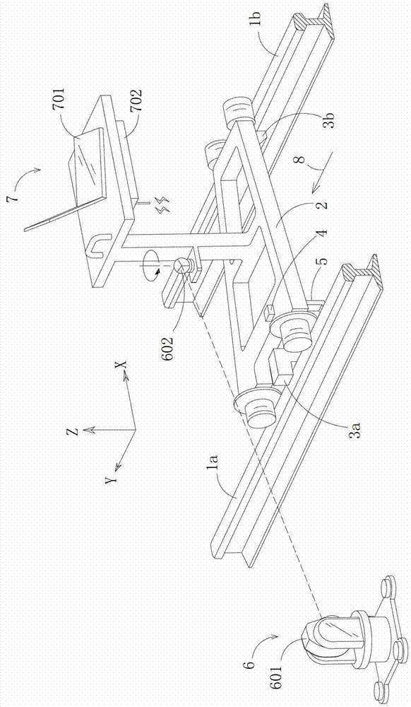
[0024] First of all, the terms "front", "rear", "left" and "right" in the present invention are all based on the relationship of the drawings. Among them, such as figure 1As shown, in the coordinate system defined by the X-axis, Y-axis and Z-axis, the Y-axis direction corresponds to the terms "front" and "rear", and the X-axis direction corresponds to the terms "left" and "right".

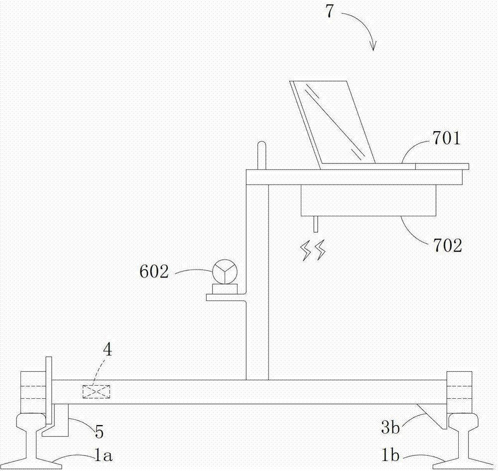
[0025] Such as figure 1 , 2 As shown, the car body of the rail car 2 is a structure with a wide left and a narrow right. The front and rear ends of the left side of the rail car 2 are respectively provided with wheels with rims. Because the magnetic element 5 applies a magnetic force to the inner side of the left rail 1a, the rims of the two wheels on the left side of the rail car 2 are close to the inner wall of the rail head of the left rail 1a, and the laser three-dimensional contour scanning device 3a on the left rail side is located at these two ends. Between the magnetic elements 5; the fr...


PUM


Abstract

The invention discloses a multifunctional rail measuring system and a method thereof. The multifunctional rail measuring system comprises a rail car, a level gauge, a three-dimensional measuring device and a data processing terminal. The left side of the rail car is provided with a left rail side laser three-dimensional contour scanning device. The left rail side laser three-dimensional contour scanning device is provided with a laser transmitter and a laser receiver corresponding to the laser transmitter, wherein the laser transmitter gives out a scanning laser band which points to the inner side of the left rail and at least covers the portion from the rail top to the combination part of the rail head and the rail waist. The right side of the rail car is provided with a right rail side laser three-dimensional contour scanning device, and the relative location between the left rail side laser three-dimensional contour scanning device and the right rail side laser three-dimensional contour scanning device has been calibrated. The right rail side laser three-dimensional contour scanning device is provided with a laser transmitter and a laser receiver corresponding to the laser transmitter, wherein the laser transmitter gives out a scanning laser band which points to the inner side of the right rail and at least covers the portion from the rail top to the combination part of the rail head and the rail waist. After measuring signals are received and processed by the data processing terminal, at least rail gauge, superelevation, rail direction and rail surface contour measured values of a measured rail can be obtained.

Description

technical field [0001] The invention relates to a track measurement system and method, in particular to a railway transportation track measurement system and method. Background technique [0002] One known railway transportation track measurement system is the GRP track measurement system offered by Amberg Technologies. The system is mainly composed of a rail car that is placed on the left and right rails and moves along the direction of the track, Leica TPS series total station, gauge sensor, superelevation sensor and odometer sensor installed on the rail car, and data Composed of devices such as processing terminals. The disadvantage of this track measurement system is the lack of scanning measurement of the rail surface profile; and the total station does not track and measure the angle and distance of the reflective prism installed on the rail car in real time, resulting in the measurement accuracy of the track direction not tall. Contents of the invention [0003] ...

Claims


Application Information

Patent Timeline
IPC IPC(8): G01B11/24G01B11/14G01B11/03G01C9/00
Inventor 卡姆·刘
Owner API ZC PRECISION INSTUMENT CO LTD
Why Eureka
Try Eureka