Polarization reflection measuring system and structure parameter measuring method

A measurement system, a technology of polarized reflection, applied in scattering characteristic measurement, measurement device, color/spectral characteristic measurement, etc., can solve the problems of reducing the measurement accuracy of the instrument, increasing the measurement error of the instrument system, and inability to detect, so as not to affect the measurement. Accuracy, improve measurement accuracy, reduce the effect of calibration error

Pending Publication Date: 2021-04-30
HUAZHONG UNIV OF SCI & TECH
View PDF0 Cites 3 Cited by
  • Summary
  • Abstract
  • Description
  • Claims
  • Application Information

AI Technical Summary

Problems solved by technology

These problems also limit the manufacturing capacity in the MEMS field and the ability to serve high-tech industries, and limit the development of high-precision measurement fields such as instrumentation industry and aerospace.
[0003] At present, there is little mention of similar designs of imaging reflective polarimeters. In addition, many reflective polarimeters need to form polarized light and detect polarized light in the entire measurement optical system, so their design requires two polarizers, and many of them need to use Rotate the device, which will not only increase the cost of the instrument, but also increase the measurement error of the instrument system and reduce the measurement accuracy of the instrument
[0004] The current common polarized reflectometer design does not combine imaging functions, which means that it cannot detect a certain measurement area of ​​the prototype to be tested, and can only select the same point to repeat the side face or measure multiple points to select the average value
In this way, a large error will often be caused when detecting a non-uniform sample to be tested, and it is impossible to complete the measurement specific to a specific point of the sample to be tested.
In addition, when measuring some periodic structures, the rigorous coupled wave analysis (RCWA) is generally used. This method has high measurement accuracy and short measurement time when measuring sub-wavelength structures, but it is strictly strict when measuring micron complex morphology structures. Due to the improvement of the Fourier series, the coupled wave analysis method will gradually lose its measurement advantages

Method used


Image

  • Polarization reflection measuring system and structure parameter measuring method
  • Polarization reflection measuring system and structure parameter measuring method
  • Polarization reflection measuring system and structure parameter measuring method

Examples


Embodiment Construction

[0033] In order to make the object, technical solution and advantages of the present invention clearer, the present invention will be further described in detail below in conjunction with the accompanying drawings and embodiments. It should be understood that the specific embodiments described here are only used to explain the present invention, not to limit the present invention. In addition, the technical features involved in the various embodiments of the present invention described below can be combined with each other as long as they do not constitute a conflict with each other.

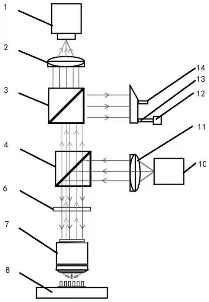
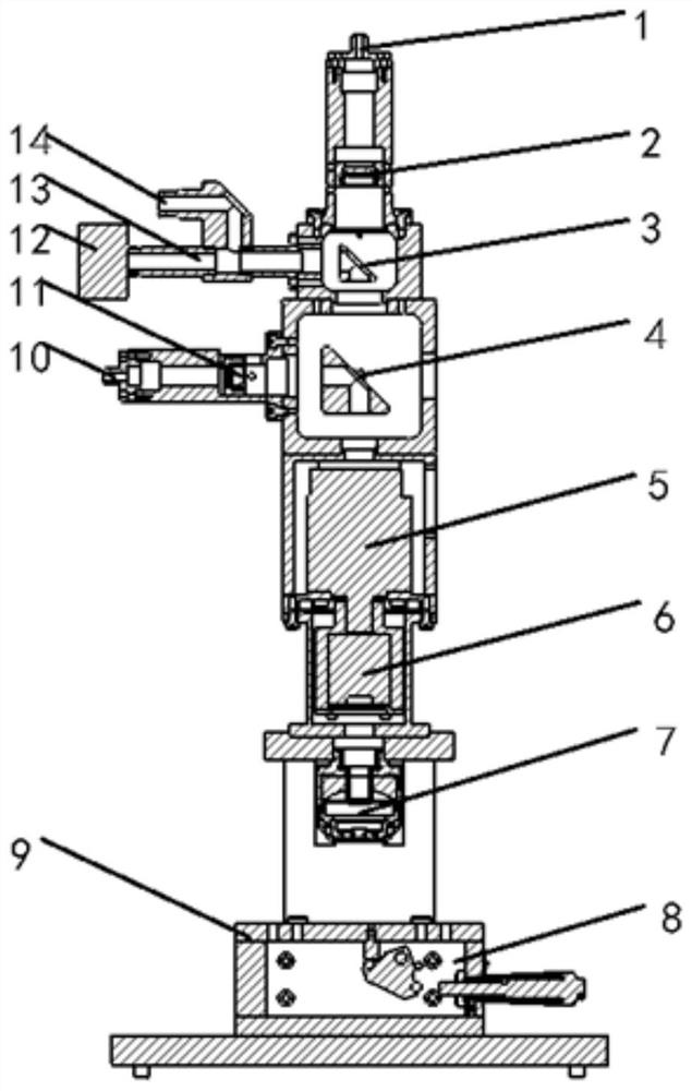
[0034] A polarized reflection measurement system provided by an embodiment of the present invention, such as Figure 1 to Figure 5 As shown, it includes a spectrometer detector 1, a focusing lens 2, a first beam splitter 3, a second beam splitter 4, a polarizer 6, a reflective objective lens 7 and a sample stage 9 coaxially arranged from top to bottom, wherein:

[0035] One side of the first sp...


PUM


Abstract

The invention belongs to the field of semiconductor testing and measuring, and particularly discloses a polarization reflection measuring system and a structural parameter measuring method, which comprise a spectrograph detector, a focusing lens, a first spectroscope, a second spectroscope, a polarizing film, a reflection type objective lens and a sample table which are coaxially arranged from top to bottom, an illumination light source, a tube mirror and a CCD camera are arranged on one side of the first spectroscope, and illumination light of the illumination light source passes through the first spectroscope, the second spectroscope, the polarizing film, the reflective objective lens and the sample to be detected, then returns along the same path and is converged into the CCD camera through the tube mirror for imaging; and a measuring light source and a collimating lens are arranged on one side of the second spectroscope, and measuring light of the measuring light source passes through the collimating lens, the second spectroscope, the polarizing film, the reflective objective lens and the to-be-measured sample, then returns to the second spectroscope along the same path and is guided into the spectrograph detector by the focusing lens. The imaging light path is added and the position of the polaroid is adjusted so that the measurement area can be accurately represented and the measurement precision can be enhanced.

Description

technical field [0001] The invention belongs to the field of semiconductor test and measurement, and more specifically relates to a polarized reflection measurement system and a structural parameter measurement method. Background technique [0002] At present, for micro-electromechanical systems (MEMS), there are still many deficiencies in design technology, packaging and testing technology, equipment technology, etc., such as low reliability of sensors, sensor packaging and testing have not yet formed a series, standard and unified interface. These problems also limit the manufacturing capabilities in the MEMS field and the ability to serve high-tech industries, and limit the development of high-precision measurement fields such as instrumentation industry and aerospace. [0003] At present, there is little mention of similar designs of imaging reflective polarimeters. In addition, many reflective polarimeters need to form polarized light and detect polarized light in the e...

Claims


Application Information

Patent Timeline
Patent Type & Authority Applications(China)
IPC IPC(8): G01N21/21G01N21/27G01N21/25G01N21/47G01N21/01
CPCG01N21/01G01N21/21G01N21/255G01N21/27G01N21/47G01N2021/0112
Inventor 张传维王鑫辉姚远刘世元
Owner HUAZHONG UNIV OF SCI & TECH
Why Eureka
Try Eureka