In-situ test system and method of lane filler bearing property

An in-situ testing and filling technology, which is applied in the direction of applying stable tension/pressure to test the strength of materials, can solve the problem that it cannot accurately reflect the real bearing performance of the filling wall on site, and it is difficult to consider the contact between filling materials. There are no relevant literature reports and other problems, to achieve the effect of eliminating the size effect, simple structure, convenient disassembly and assembly

Active Publication Date: 2013-05-22
SHANDONG UNIV OF SCI & TECH
View PDF4 Cites 10 Cited by
  • Summary
  • Abstract
  • Description
  • Claims
  • Application Information

AI Technical Summary

Problems solved by technology

This inevitably brings about two problems: (1) Compared with the field, the size of the test piece produced in the laboratory is not only smaller in plane scale, but also has a certain difference in height, and it is difficult to take into account the filling material The test results cannot accurately reflect the real bearing performance of the filling wall on site; (2) The roadside filling body is stacked on the roadway bottom plate in the field, and the support for the roof is provided by the “filling body -Baseboard" system shared, and it is difficult to test such a system in the laboratory
[0004] Therefore, downhole in-situ testing is an effective method to accurately and quickly obtain the bearing capacity of gob-side entry filling body, and this method has not been reported in the relevant literature so far.

Method used


Image

  • In-situ test system and method of lane filler bearing property
  • In-situ test system and method of lane filler bearing property
  • In-situ test system and method of lane filler bearing property

Examples


Embodiment Construction

[0044] The embodiments of the present invention will be further described below with reference to the accompanying drawings.

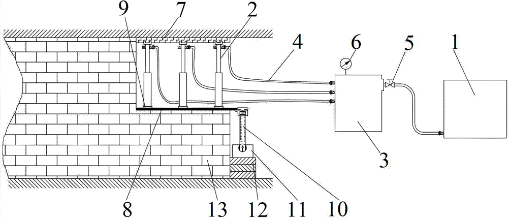
[0045] From figure 1 It can be seen that the embodiment of the in-situ testing system of the present invention is composed of a loading control system, a pressure support system and a displacement measurement system, wherein:

[0046] The loading system is composed of an emulsion pump station 1, a loading control box 3 and six single hydraulic props 2 connected; the loading control box 3 is a high-pressure oil tank with a liquid inlet and a plurality of liquid outlets; The liquid port is connected to the emulsion pump station 1 through the liquid inlet valve 5, and each liquid outlet is connected to the corresponding single hydraulic prop 2 through the high-pressure oil pipe 4; a high-pressure oil tank is connected to reflect the supporting force of the single hydraulic prop 2 The pressure gauge 6;

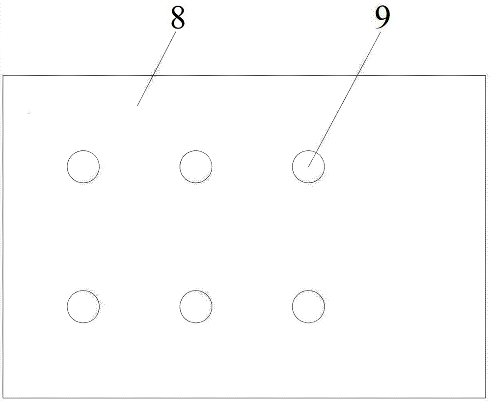
[0047] The pressure support system includes a top ...


PUM

PropertyMeasurementUnit
heightaaaaaaaaaa
widthaaaaaaaaaa
lengthaaaaaaaaaa

Abstract

The invention discloses an in-situ test system and method of lane filler bearing property. The in-situ test system comprises a loading control system, a pressure support system and a displacement measurement system, wherein the loading control system applies a pressure to the pressure support system; in a pressure-applying process, a vernier caliper of the displacement measurement system records a corresponding pressure value of a pressure meter when moving for a certain distance; stress values and strain values of a filler in different moments in a loading process are converted through the pressure value and the displacement value; and a stress-strain relation curve of the filler in the loading process is made according to the stress values and the strain values so as to determine bearing performance parameters such as compressive strength and deformation modulus of the lane filler. According to the in-situ test system and method, the influences caused by the size effect and a test environment and the like during testing in a laboratory are fundamentally eliminated, and the engineering mechanics properties of the filler can be actually reflected.

Description

technical field [0001] The invention relates to a technology for testing the load-bearing performance of engineering rock and soil bodies, in particular to an in-situ test technology for the load-bearing performance of roadside filling bodies. Background technique [0002] Gobside entry retention technology has always been an important technical development direction of coal mining in my country. It has a significant effect on improving the recovery rate of coal resources, reducing the rate of roadway excavation, alleviating the contradiction of mining replacement, and realizing safe and efficient mining in mines. In recent years, as the country pays more and more attention to the mine environment, the green mining technology of coal mines has been vigorously promoted, and the technology of retaining roadways along the goaf has generally begun to use the roadside filling method for roadway protection. Currently, the commonly used filling materials mainly include: concrete, M...

Claims


Application Information

Patent Timeline
Patent Type & Authority Applications(China)
IPC IPC(8): G01N3/10
Inventor 赵同彬刘长雷谭云亮马成甫刘鹏程
Owner SHANDONG UNIV OF SCI & TECH
Why Eureka
Try Eureka