

Waveguide ring coupler
A coupler and waveguide ring technology, which is applied in the field of broadband single-hole waveguide ring couplers, can solve problems such as narrow working bandwidth, and achieve the effects of wide working bandwidth, small insertion loss, and convenient processing and assembly.
- Summary
- Abstract
- Description
- Claims
- Application Information
AI Technical Summary
Problems solved by technology
Method used
Image

Examples
Embodiment 1
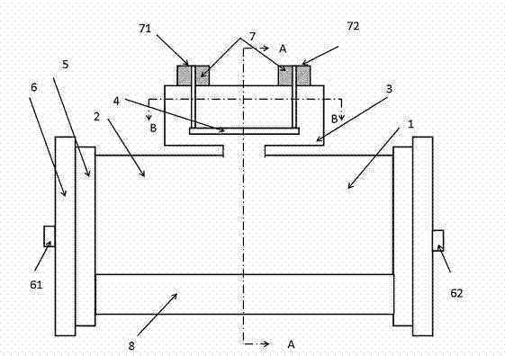
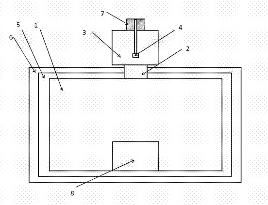
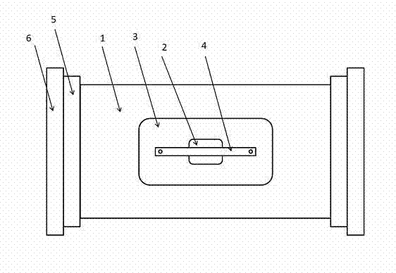
[0024] Such as figure 1 , figure 2 , image 3 As shown, a waveguide ring coupler includes a main waveguide 1, a metal ridge 8 is connected to the wide inner wall of the main waveguide 1, and a coupling hole 2 is opened on the side wall away from the metal ridge, and the coupling hole 2 of the main waveguide 1 A coupling cavity 3 is connected to the position 2, a coupling ring 4 is arranged in the coupling cavity 3, a coaxial port 7 is connected to the coupling ring 4, and the coaxial port 7 is arranged outside the coupling cavity 3; The two ends of the main waveguide 1 are also connected with a transition step 5, and the end of the transition step 5 away from the main waveguide 1 is also provided with a standard waveguide 6;
[0025] The axis of the coupling ring 4 is parallel to the axis of the main waveguide 1 .
[0026] The angle formed by the axis of the coupling ring 4 and the axis of the main waveguide 1 is greater than 5 degrees.
[0027] The cross-sectional shape ...
Embodiment 2
[0037] Such as figure 1 , Figure 4 , Figure 5 As shown, the difference between the present embodiment and the first embodiment is that the axial cross-section of the shape of the coupling cavity 3 is the original shape. The angle between the coupling hole 2, the coupling cavity 3 and the coupling ring 4 and the axial direction of the main waveguide 1 is greater than 5 degrees.
Embodiment 3
[0039] Such as figure 1 , figure 2 As shown, the difference between the present embodiment and the first embodiment is that the shape of the coupling cavity 3 is rectangular. The angle between the coupling hole 2, the coupling cavity 3 and the coupling ring 4 and the axial direction of the main waveguide 1 is greater than 5 degrees.
[0040] The main difference between the above three solutions is that a metal ridge is added to the bottom of the main waveguide 1 , that is, a metal ridge 8 is connected to the inner wall of the main waveguide 1 away from the coupling hole 2 . Whether the shape of the coupling cavity 3 is rectangular or rectangular, whether the shape of the coupling hole 2 is rectangular or rectangular, whether there is an angle between the coupling hole 2 , the coupling cavity 3 and the coupling ring 4 and the main waveguide 1 . In the specific implementation process, the size of the coupling hole 2, the size and shape of the coupling cavity 3, the size of th...
PUM
 Abstract
Description
Claims
Application Information