
Mold motor

A motor and molding technology, applied in the direction of electromechanical devices, electrical components, magnetic circuit static parts, etc., can solve the problems such as the inability of the terminal and the lead to conduct, and the terminal deformation.

Inactive Publication Date: 2013-05-22
NIDEC TECHNO MOTOR CORP
View PDF3 Cites 4 Cited by
  • Summary
  • Abstract
  • Description
  • Claims
  • Application Information

AI Technical Summary

Problems solved by technology

If the resin flows into the terminal mounting part, the terminals arranged in the terminal mounting part may be deformed by the filling pressure of the resin
If the terminal is deformed, there may be a gap between the terminal and the lead wire, making conduction impossible

Method used


Image

  • Mold motor
  • Mold motor
  • Mold motor

Examples


Embodiment approach 1

[0025] 1. Structure of the molded motor

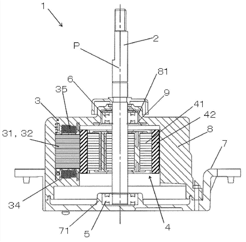
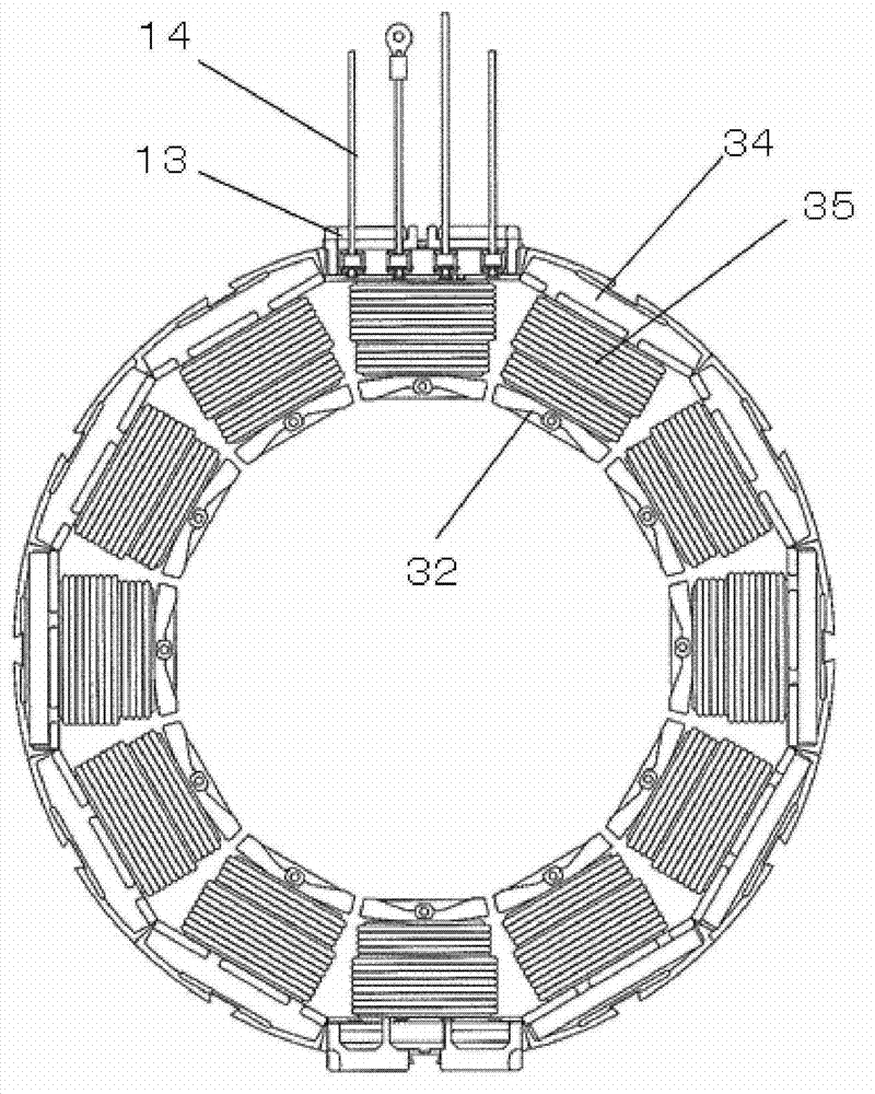
[0026] figure 1 It is a cross-sectional view showing a schematic structure of a molded motor according to an embodiment of the present invention. figure 1 The motor 1 shown is an example of a molded motor of the present invention. figure 2 is a plan view of the stator 3 .

[0027] The motor 1 includes a shaft 2 , a stator 3 , a rotor 4 , a first bearing 5 , a second bearing 6 , a motor bracket 7 , a motor housing 8 and a bearing bracket 9 . One end portion of the shaft 2 is supported by a first bearing 5 , and the central portion is supported by a second bearing 6 . The shaft 2 is rotatable with respect to the first bearing 5 and the second bearing 6 . The other end of the shaft 2 is located outside the motor 1 . The shaft 2 is equipped with a load on the other end side.

[0028] In addition, in figure 1 In , the axis P is a line extending along the center of the shaft 2 . In the following description, the direction along the ...


PUM


Abstract

The invention relates to a mold motor. A stator (3) comprises leads (14) connected with a coil (32), terminals (12) connected with the leads (14), and a terminal holder (11) for keeping the leads (14) and the terminals (12) and fixed on insulating members (34). A pair of mutually-opposed sides (11m,11n) of the terminal holder (11) comprises a first lead holding groove (11b) and a second lead holding groove (11b) for inserting the leads (14). One end part of the leads (14) is configured in the first lead holding groove (11b). The insulating members (34) has walls (37) covering the first lead holding groove (11b).

Description

technical field [0001] The present invention relates to a molded motor in which at least a stator is covered with a molding material such as resin. Background technique [0002] At least the stator of the molded motor is covered with a molding material such as resin. One example of the molded motor is disclosed in JP-A-2011-78286. The molded motor disclosed in Japanese Unexamined Patent Publication No. 2011-78286 has a terminal mounting portion on an insulating member of a stator. The terminal mounting part accommodates a plurality of terminals for connecting the coils of the stator and the lead wires connected to the control circuit. The terminal mounting portion has a hole capable of accommodating the terminal and a slit through which the coil can be inserted. The hole is covered by the cover. The outer cover has an edge. The edge part has a side wall part covering a part of the opening part of the slit groove. [0003] In the structure disclosed in Japanese Patent A...

Claims


Application Information

Patent Timeline
Patent Type & Authority Applications(China)
IPC IPC(8): H02K5/22H02K3/38
CPCH02K1/12H02K3/02H02K3/345H02K15/10H02K2203/06
Inventor 宫本将孝
Owner NIDEC TECHNO MOTOR CORP
Learn More