Piezomagnetic/piezoelectric broadband vibration energy collector adopting rotary pendulum type structure

A technology of vibration energy collection and piezoelectric transducers, which is applied in the direction of generators/motors, piezoelectric effect/electrostrictive or magnetostrictive motors, electrical components, etc., which can solve the problem of increasing the volume of the collector and reducing vibration Energy harvester output power density and other issues

Inactive Publication Date: 2013-05-22
CHINA WEST NORMAL UNIVERSITY
View PDF6 Cites 23 Cited by
  • Summary
  • Abstract
  • Description
  • Claims
  • Application Information

AI Technical Summary

Problems solved by technology

This method can obtain a wider frequency band, but at each vibration frequency, only one beam resonates, and the output power of other non-resona...

Method used


Image

  • Piezomagnetic/piezoelectric broadband vibration energy collector adopting rotary pendulum type structure
  • Piezomagnetic/piezoelectric broadband vibration energy collector adopting rotary pendulum type structure
  • Piezomagnetic/piezoelectric broadband vibration energy collector adopting rotary pendulum type structure

Examples


Embodiment 1

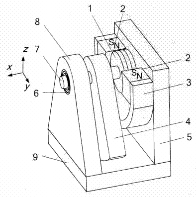
[0022] Embodiment 1, see attached figure 1 . The devices used in this embodiment include: circular piezomagnetic / piezoelectric transducer 1, permanent magnet 2, armature 3, rotary eccentric pendulum 4, frame body right support plate 5, bearing 6, cantilever beam 7, gate type Frame left support plate 8, frame base 9.

[0023] This embodiment is a structure in the scheme, that is, a cantilever beam 7 supported by a bearing 6 is installed on the left support plate 8 of the door frame, and one end of the cantilever beam 7 protruding is coaxially equipped with a rotating eccentric pendulum 4 and a pressure magnet / The piezoelectric transducer 1 and the rotating eccentric pendulum 4 can swing freely and even rotate, while the piezoelectric / piezoelectric transducer 1 is installed in the air gap of the magnetic circuit composed of two permanent magnets 2, and the permanent magnet 2 consists of a The armature 3 is supported by the magnetic conductor. The armature 3 is fixed on the ri...

Embodiment 2

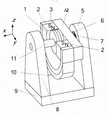
[0030] Embodiment 2, see attached figure 2 . As another structure in the scheme, the left support plate 8 supports the piezoelectric / piezoelectric transducer 1 by a fixed shaft 11, a permanent magnet 2 is supported by a cantilever beam supported by a bearing, and the piezoelectric / piezoelectric transducer The transducer 1 is fixed in the air gap formed by the permanent magnet magnetic circuit. The difference between this structure and the embodiment 1 is that the permanent magnet rotates, but the transducer does not move, so as to achieve the same effect.

[0031] The eccentric pendulum is composed of a magnet 2 , an armature 3 and a mass 10 . They are connected by bonding. The mass block 10 can also be removed from the eccentric pendulum, and the eccentric pendulum can be formed by increasing the mass of the armature 3 . The eccentric pendulum is fixedly connected with the magnetic circuit fixed plate 12, and the magnetic circuit fixed plate 12 is fixedly connected with the...


PUM


Abstract

The invention discloses a piezomagnetic/piezoelectric broadband vibration energy collector adopting a rotary pendulum type structure. The energy collector is characterized in that a door type frame is designed, a hole is arranged at the upper end of a left supporting plate (8) of the frame, a bearing (6) is mounted in the hole, a cantilever beam (7) is mounted in the bearing, one extended-out end of the cantilever beam sequentially penetrates into a sway hole of a rotary type eccentric pendulum (4) and then is fixedly connected with a piezomagnetic/piezoelectric energy converter (1), the piezomagnetic/piezoelectric energy converter is embedded in an air gap formed by a pair of permanent magnets (2), an armature (3) connected with the permanent magnets is fixed on a right supporting plate (5), or one extended-out end of the cantilever beam (7) supported by the bearing is connected with a fixing plate (12) of the pair of the permanent magnets (2), the piezomagnetic/piezoelectric energy converter is embedded in an air gap formed by the permanent magnets (2), and a central shaft of the piezomagnetic/piezoelectric energy converter is fixed on the left supporting plate (8) of the door type frame.

Description

technical field [0001] The invention relates to a device in the field of energy technology, in particular to a piezoelectric / piezoelectric broadband vibration energy collection device using a rotating pendulum structure. Background technique [0002] Vibration is a ubiquitous phenomenon in the environment. It is widely present in various production and living equipment such as bridges, buildings, ships, vehicles, machine tools, household appliances (refrigerators, washing machines, microwave ovens), and also in the blood flow of the human body, the heart, etc. In life processes such as beating and limb movement. If the vibration in the environment is converted into electrical energy, it will have a very broad application prospect for powering low-power devices such as wireless networks and embedded systems. [0003] The vibration in the environment is usually not a single frequency vibration, its frequency components are often distributed in a wide frequency band. In order...

Claims


Application Information

Patent Timeline
IPC IPC(8): H02N2/18
Inventor 代显智张章王勇肖顺文张谦述刘汉奎戚准兵
Owner CHINA WEST NORMAL UNIVERSITY
Why Eureka
Try Eureka