Method for operating a resonance measuring system

A technology of resonance measurement and measurement tube, which is used in the field of running resonance measurement systems and can solve problems such as measurement inaccuracy

Active Publication Date: 2013-05-22
KROHNE MESSTECHNICK GMBH & CO KG
View PDF6 Cites 5 Cited by
  • Summary
  • Abstract
  • Description
  • Claims
  • Application Information

AI Technical Summary

Problems solved by technology

[0007] It is known that significant measurement inaccuracies arise when applying multiphase flows, so it is of great interest to be able to reliably detect the presence of multiphase flows

Method used


Image

  • Method for operating a resonance measuring system
  • Method for operating a resonance measuring system
  • Method for operating a resonance measuring system

Examples


Embodiment Construction

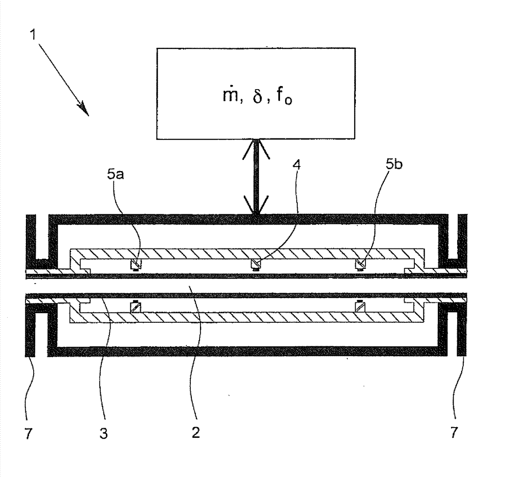
[0029] In FIG. 1 , a resonant measuring system structurally based on the known form of a Coriolis flow measuring device 1 with a measuring tube 3 through which a medium 2 flows, an oscillation generator 4 and vibration pickup is shown in full schematic form. 5a, 5b and a control and analysis unit 6. The vibration pickups 5a, 5b do not have to be arranged on both sides of the measuring tube, of course.

[0030] The oscillation generator 4 excites the measuring tube 3 to oscillate with a predetermined excitation frequency and a first amplitude, which is functionally required in a Coriolis flow measuring device for carrying out basic flow measurements. The excitation-induced oscillations of measuring tube 3 are detected by vibration pickups 5 a , 5 b , wherein the material flow through measuring tube 3 is derived from the phase difference and thus the time difference between the left and right oscillations of measuring tube 3 .

[0031] The control and analysis unit 6 is connect...


PUM


Abstract

The method involves determining a measured value for an amplitude-dependent state variable of a multi-phase medium (2). The measured value is determined from a recorded resulting vibration by using a control and evaluation unit. A measuring tube (3) is excited by a vibrator (4) to oscillate with different excitation frequency. An independent claim is also included for a resonant measuring system.

Description

technical field [0001] The invention relates to a method for operating a resonant measuring system, in particular in the form of a Coriolis flow measuring device or a density measuring device, wherein the resonant measuring system has at least one measuring tube through which a medium flows, at least An oscillation generator, at least one vibration pickup and at least one control and analysis unit, wherein the oscillation generator excites the measuring tube to oscillate with a predetermined excitation frequency and a first amplitude and detects the resulting oscillation of the measuring tube via the at least one vibration pickup . The invention also relates to a resonant system, in particular in the form of a Coriolis flow measuring device or a density measuring device, which is operated with the method described above. Background technique [0002] The aforementioned resonant measuring systems have been known not only in the form of Coriolis flow measuring devices but als...

Claims


Application Information

Patent Timeline
Patent Type & Authority Applications(China)
IPC IPC(8): G01F1/74G01F1/84
CPCG01F1/8468G01F1/849G01F1/8422G01F1/74G01F1/8413G01F1/8436G01N9/002
Inventor K.科拉希R.施托姆
Owner KROHNE MESSTECHNICK GMBH & CO KG
Why Eureka
Try Eureka