
Device for optical axis alignment for image capturing and method for aligning an optical axis

A technology for image shooting and axis adjustment, applied in optics, photography, optical components, etc., can solve problems such as dizziness, difficult and cumbersome adjustment of optical axis level

Inactive Publication Date: 2013-05-22
CINETOOLS
View PDF5 Cites 7 Cited by
  • Summary
  • Abstract
  • Description
  • Claims
  • Application Information

AI Technical Summary

Problems solved by technology

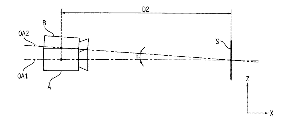
[0015] In order to eliminate this vertical error f, even if the rig of the corresponding camera is adjusted, due to the error of the rig itself of the left-eye and right-eye cameras A and B, the position of the non-adjustment mark board S will reflect the difference of the optical axis. Leveling is very difficult job
[0016] Therefore, in practice, the adjustment state of the optical axis is confirmed using a plurality of index substrates S at predetermined intervals, but this is a very cumbersome operation, which has the disadvantage of prolonging the overall imaging time.
[0017] Therefore, a certain degree of follow-up correction work should be considered to shoot stereoscopic images. However, even if the vertical error r of this optical axis adjustment is very small, it will be induced under the conditions of displaying stereoscopic images on a large screen such as a movie. From the viewpoint of eye fatigue and dizziness of viewers, it is urgent to ensure high image quality of stereoscopic images through optical axis adjustment

Method used


Image

  • Device for optical axis alignment for image capturing and method for aligning an optical axis
  • Device for optical axis alignment for image capturing and method for aligning an optical axis
  • Device for optical axis alignment for image capturing and method for aligning an optical axis

Examples


Embodiment Construction

[0126] A preferred embodiment of the optical axis adjustment device for stereoscopic image shooting of the present invention will be described below.

[0127] The advantages and features of the present invention and methods for achieving them will become more apparent with reference to the following drawings and detailed descriptions of the embodiments.

[0128]However, the present invention is not limited by the following disclosed embodiments, but is embodied in various forms that are different from each other. This embodiment is only used to make the disclosure of the present invention more complete, so that those skilled in the art to which the present invention belongs can fully Understanding the scope of the invention, the invention is only defined by the scope of the claims.

[0129] In addition, in the process of describing the present invention, if it is judged that related known technologies may obscure the gist of the present invention, the detailed description ther...


PUM


Abstract

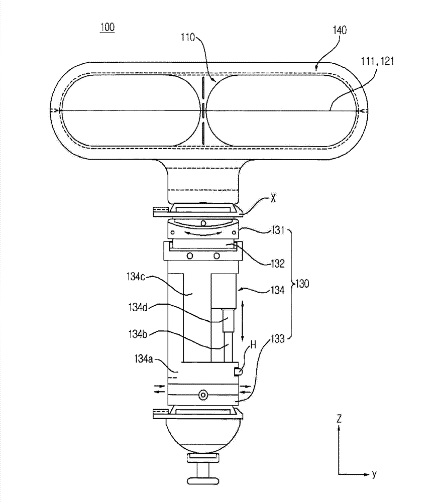
The present invention relates to a device for optical axis alignment for capturing a stereoscopic image. The device for optical axis alignment for capturing a stereoscopic image, which assists the optical axes of the left and right eye cameras, which are spaced horizontally from each other, to be disposed on the same plane, includes: a first reference unit spaced from and opposite to the left and right eye cameras, forming a first reference line, and having a see-through transparent property; a second reference unit spaced from and opposite to the first reference unit and forming a second reference line on the same plane as the first reference unit;,and an alignment unit transferring the first reference unit and the second reference unit to allow the optical axis of one of the left and right eye cameras to be disposed on the same plane formed by the first reference line and the second reference line. According to the present invention, provided is an optical aligning device for capturing a stereoscopic image. Therefore, vertical errors that occur while an optical alignment is performed using a typical signboard may be removed, and accordingly, capturing a stereoscopic image with accuracy may be possible.

Description

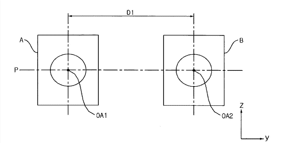
technical field [0001] The invention relates to an adjustment device and an adjustment method, in particular to an optical axis adjustment device and an optical axis adjustment method of a camera for shooting images. Background technique [0002] A human perceives a three-dimensional effect due to parallax between the left and right eyes, that is, a difference in information seen by the left and right eyes. Therefore, in order to reflect stereoscopic images, two cameras are generally used for shooting. [0003] In the attached picture, figure 1 It is a schematic front view showing the state of horizontal adjustment of the optical axes of the left-eye and right-eye cameras configured to shoot stereoscopic images, figure 2 It is a conceptual diagram illustrating errors that occur when the optical axes of the left-eye and right-eye cameras are not adjusted horizontally when shooting stereoscopic images. [0004] When the line connecting the center of the camera lens and the...

Claims


Application Information

Patent Timeline
Patent Type & Authority Applications(China)
IPC IPC(8): G03B35/04G03B35/00
CPCG03B35/00G03B35/04H04N13/0246G03B35/08G02B27/644H04N13/246G03B35/20
Inventor 许成龙
Owner CINETOOLS
Learn More