Continuous cladding method and device of obtuse angle flowing channel

A technology of flow channels and obtuse angles, which is applied in the field of continuous coating and coating equipment of obtuse angle flow channels, and can solve the problems of high temperature and large extrusion force of blocking blocks

Inactive Publication Date: 2013-05-29
DALIAN JIAOTONG UNIVERSITY
View PDF11 Cites 10 Cited by
  • Summary
  • Abstract
  • Description
  • Claims
  • Application Information

AI Technical Summary

Problems solved by technology

[0002] The feed hole on the traditional continuous coating tool is in the radial direction of the extrusion wheel. Sometimes in order to improve the strength of the block, the direction of the feed hole will be offset by a certain angle. The center line of the cavity feed hole and the extrusion wheel The angle β of the point tangent line is 90° or an acute angle less than 90°. The advantage of this is that the block is in a good stress state and can improve the service life of the block. The disadvantage is that the temperature of the block is high and the extrusion force Big

Method used


Image

  • Continuous cladding method and device of obtuse angle flowing channel
  • Continuous cladding method and device of obtuse angle flowing channel
  • Continuous cladding method and device of obtuse angle flowing channel

Examples


Embodiment Construction

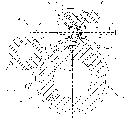
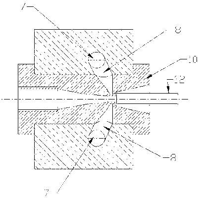
[0024] Such as figure 1 , figure 2 , image 3 and Figure 4 As shown, the continuous coating method of the obtuse angle flow channel, the rotating extrusion wheel 1 has grooves 2 in the circumferential direction, the billet 3 is pressed down by the compacting wheel 4, and the friction between the billet 3 and the groove 2 of the extrusion wheel Driven by force, when the blank 3 advances to the block 6, it enters the feed hole 7 of the extrusion cavity. At the end of the feed hole 7, there is a metal flow channel 8 at an obtuse angle greater than 95° with the center line of the mold. When the metal flows The end of the channel 8 is an overmolded metal cavity 9, a metal flow rate shunt 11 is installed in front of the die 10, the product 12 is extruded through the annular gap formed by the die 10 and the punch 13, and the core wire 14 passes through the punch 13. Penetrate and extrude the cladding metal to form a cladding layer outside the core wire; figure 1 Among them, poi...


PUM

PropertyMeasurementUnit
angleaaaaaaaaaa

Abstract

The invention discloses a continuous cladding method of an obtuse angle flowing channel. The continuous cladding method comprises the following steps that: a, under the compaction of a compaction wheel, a blank enters an extruding cavity through a friction force between a rotary extruding wheel groove and the blank; b, when the blank advances to a baffle block, the blank enters an extruding cavity feeding hole, wherein the center line of the extruding cavity feeding hole is in a chord line direction of an extruding wheel in a non-radius direction; and c, a metal flowing channel forming the obtuse angle with the cavity feeding hole is arranged at the tail end of the extruding cavity feeding hole, a cladding forming metal containing cavity is arranged at the tail end of the metal flowing channel, a female die and a male die are arranged at the tail end of the cladding forming metal containing cavity, a metal flow velocity splitter is arranged between the female die and the male die, a product is extruded through a circular seam formed by the female die and the male die, a core wire is transferred in through a center circular hole in the male die, and a cladding metal is extruded to form a cladding layer outside the core wire. According to the continuous cladding method, by adopting the blank and through one group of flowing channels with obtuse angles of more than 95 DEG, the metal is extruded to form different cable cladding products through the dies.

Description

technical field [0001] The invention relates to a continuous coating method of an obtuse angle flow channel. Background technique [0002] The feed hole on the traditional continuous coating tool is in the radial direction of the extrusion wheel. Sometimes in order to improve the strength of the block, the direction of the feed hole will be offset by a certain angle. The center line of the cavity feed hole and the extrusion wheel The angle β of the point tangent line is 90° or an acute angle less than 90°. The advantage of this is that the block is in a good stress state and can improve the service life of the block. The disadvantage is that the temperature of the block is high and the extrusion force Big. [0003] In the traditional continuous coating method, after the metal billet enters the cavity of the cavity, the metal billet needs to turn a 90° right-angle bend in the opposite direction to the extrusion wheel, and enter the forming mold; continuous equal-channel angu...

Claims


Application Information

Patent Timeline
Patent Type & Authority Applications(China)
IPC IPC(8): B21C23/30
Inventor 刘元文宋宝韫
Owner DALIAN JIAOTONG UNIVERSITY
Why Eureka
Try Eureka