Steel wire handle forming mechanism

A steel wire, hand and foot technology, applied in the field of metal wire bending and forming machinery, can solve the problems of no reference value for processing steel wire handles, unfavorable mass and rapid production, and lack of forming steel wire handles, saving labor resources, operation and maintenance. Convenience and the effect of reducing manpower input

Inactive Publication Date: 2014-12-24
上海金熟新材料科技股份有限公司
View PDF7 Cites 0 Cited by
  • Summary
  • Abstract
  • Description
  • Claims
  • Application Information

AI Technical Summary

Problems solved by technology

For this reason, the applicant has searched the literature, and the Chinese Patent Authorization Announcement No. CN101536878B recommends "handles for household appliances and their production molds and production methods". The steel wire handle used has no reference significance, especially because only one handle can be formed at a time, so the efficiency is low, which is not conducive to industrialized mass production; Progressive mold", the patent structure is complex and has a specific pertinence that can only form the handle of the pot lid, so it has no enlightening significance for the forming of the steel wire handle; and, the authorized announcement number CN202490885U introduces "a U-shaped bending die ", this patent can embody the strengths described in columns 0015 to 0019 of its description, and form a U-shaped workpiece at one time (the patent indicates which occasion the workpiece is used for), but it is not suitable for the forming of steel wire handles. And because only one U-shaped workpiece can be obtained at a time, the efficiency is low; also, the authorized announcement number CN202199698U discloses a "bending device for single pressing and multi-bending". Processing steel wire handles has no reference value, and can only obtain one workpiece at a time, so the efficiency is low; moreover, the "mesh bar automatic bending forming machine" announced by the publication number CN102172738A, the "mesh sheet automatic bending forming machine" announced by CN102172739A " and CN102172740A discloses " mesh bar automatic bending machine " all is the mesh bending of hollow-out shape for the temporary use trolley and shopping basket etc.

Method used


Image

  • Steel wire handle forming mechanism
  • Steel wire handle forming mechanism

Examples


Embodiment Construction

[0021] In order to enable the examiner of the Patent Office, especially the public to understand the essence and beneficial effects of the invention, the applicant will explain it in detail in the form of embodiments, but the description of the embodiments is not a plan for the invention plan.Restrictions, any formal but immoral equivalent transformation based on the concept of the present invention should be regarded as the technical solution category of the present invention.

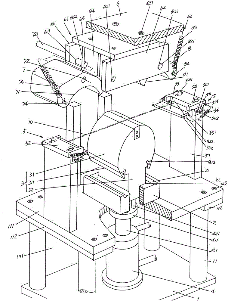
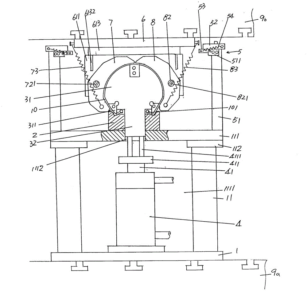
[0022] See figure 1 and figure 2 , Give a bottom 1, according to the common sense of public knowledge, the base 1 is fixed with the working platform of the hydraulic machine in the use state. Specifically, the hydraulic prescription base of the hydraulic machine 9A ( figure 2 Show) Fixed, that is, configure it on the underwriter base 9A.The hydraulic machine mentioned here is preferred rather than limited to the type of Y32-305 hydraulic press produced by the forging machine tool factory in Xuzhou City, C...


PUM


Abstract

A steel wire handle forming mechanism belongs to metal steel wire bending and forming machinery. The steel wire handle forming mechanism comprises a base, an acting cylinder, and an upper die frame. A group of stand columns are fixed on one side of the base, a lower die frame is fixed on the tops of the group of stand columns, and a demising cavity is formed in the middle of the lower die frame. A die head seat is fixed with the lower die frame. The upper surfaces of the die head seat are respectively provided with a handle foot forming groove, and the middle of the die head seat forms a die handle matching cavity. A die head is composed of a semi-cylinder and a die handle. Two sides of the semi-cylinder are respectively provided with a handle foot forming die slot, and handle foot forming dies are inserted in the handle foot forming die slots in an embedded mode. The die handle is formed on one side of the semi-cylinder. The acting cylinder is fixed on the base. Two steel wire placing devices are arranged on two sides of the lower die frame, wherein the two sides of the lower die frame face upwards. A crossing arm frame is fixed on one side of the upper die frame. A first crossing arm and a second crossing arm are connected on two ends of the crossing arm frame and connected with two sides of the upper die frame, and then a first crossing arm arc cavity and a second crossing arm arc cavity are formed respectively. Manipulation strength is lightened, efficiency is improved, quality is guaranteed, operation and maintenance are convenient, and cost is saved.

Description

Technical field [0001] The present invention belongs to the field of metal steel wire bending and forming machinery technology, which involves a kind of steel wire lifting and shaping mechanism, which is used to form a container such as coating barrels, paint cans, paint buckets, daily life buckets and other containers.Steel wire lifting. Background technique [0002] Zhou Zhi is not limited to the containers raised above, which are equipped with metal iron wire with the grip of the grip.The shape of the handle is special, and the specific manifestations are the inflection point and / or the arc transition point, which requires strict requirements on the forming process.In addition, because the handle is a non -standard product, it is not possible to obtain a dedicated forming equipment on the market channels. [0003] At present, the formation of the above -mentioned handles is mostly relying on the workers with their own mold bending. The specifically fixed the corresponding modu...

Claims


Application Information

Patent Timeline
Patent Type & Authority Patents(China)
IPC IPC(8): B21F45/00B21F1/00
Inventor 朱惠琴
Owner 上海金熟新材料科技股份有限公司
Why Eureka
Try Eureka