Rear derailleur

A transmission and connecting rod technology, applied in vehicle gearboxes, chain/belt transmissions, transportation and packaging, etc., can solve the problems of user inconvenience, easy to be contaminated with sand, difficult to clean, etc.

Inactive Publication Date: 2013-05-29
林昌慧
View PDF7 Cites 5 Cited by
  • Summary
  • Abstract
  • Description
  • Claims
  • Application Information

AI Technical Summary

Problems solved by technology

And if the speed changer moves back (loosen the speed change cable), the spring will gradually return to its original state (without force), and with the elastic force of its return, the movement of the buckle chain steering wheel will be gradually connected with the gear back down. The position of the lever comes to the smaller flywheel chainring (at this time, the force required for pedaling becomes larger), in view of this, someone in the market has invented a reverse rear derailleur, and its action principle is just opposite to that of the forward type, that is, when When the transmission is in action (rolling the transmission cable), as the transmission gear is shifted, the position of the movable link of the chain steering wheel moves to the direction of the smaller chainring in the flywheel in sequence. The return elasticity of the spring on the rod can make the position of the movable link of the chain steering wheel move to the direction of the larger chainring in the flywheel in sequence, so it can save effort when climbing a slope, regardless of whether it is a forward or reverse cantilever linkage. The rod-spring type rear derailleurs have a common disadvantage, that is, the spring and the connecting rod are exposed during the movement, and they are easy to be contaminated with sand and even weeds during the shifting process, which is not only difficult to clean, but also easily damages the shifting system. Failure, and easy to get off the chain, causing inconvenience to the user

Method used


Image

  • Rear derailleur
  • Rear derailleur
  • Rear derailleur

Examples


Embodiment Construction

[0055] In order to further explain the technical solution of the present invention, the present invention will be described in detail below through specific examples.

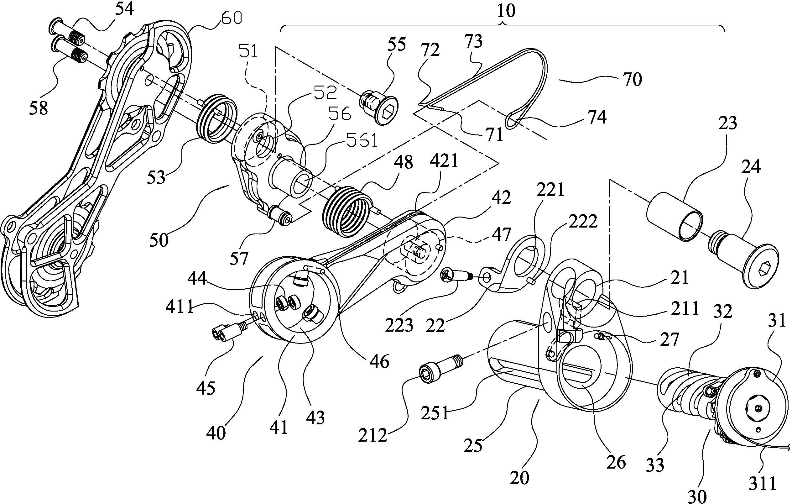
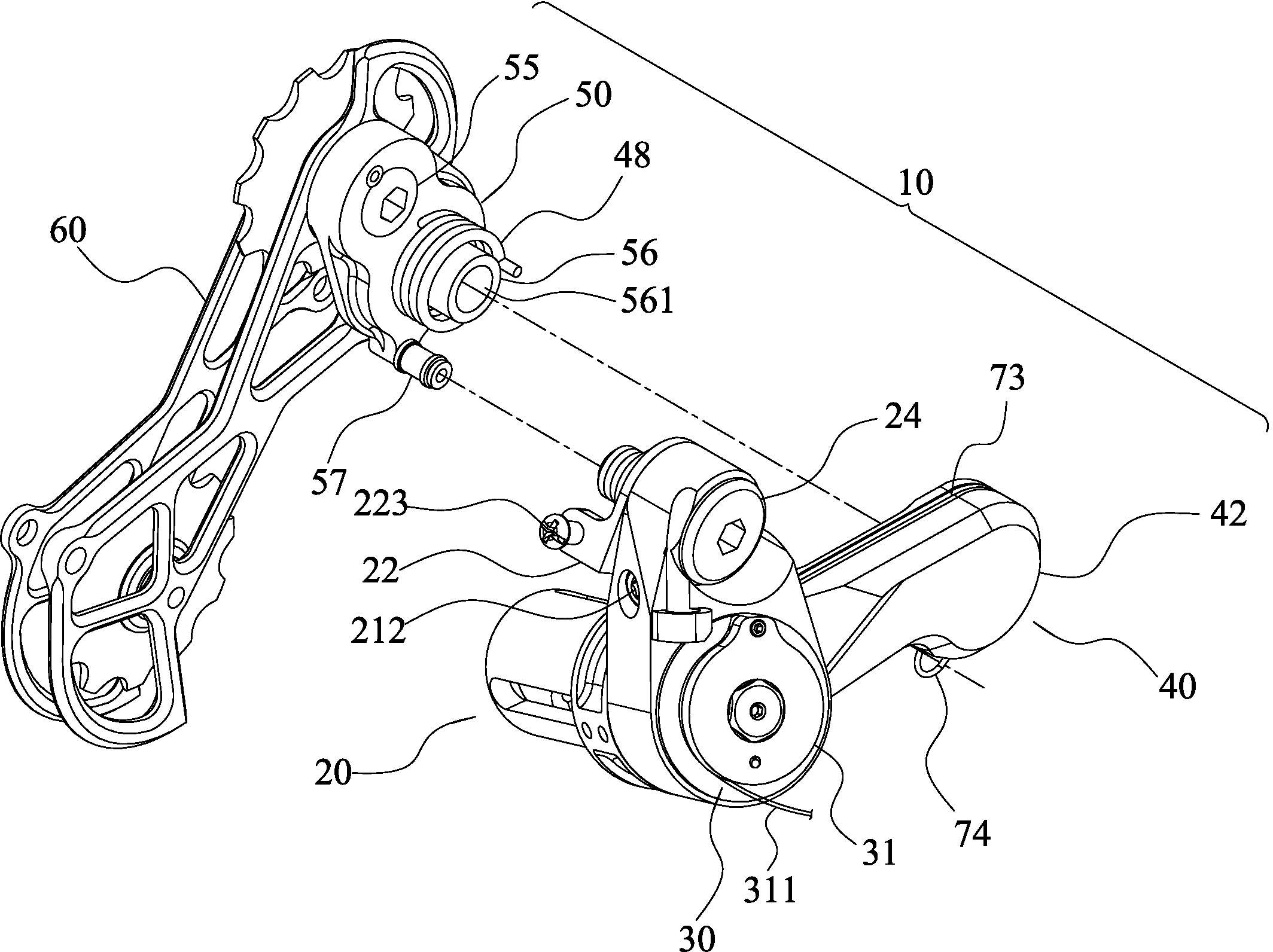
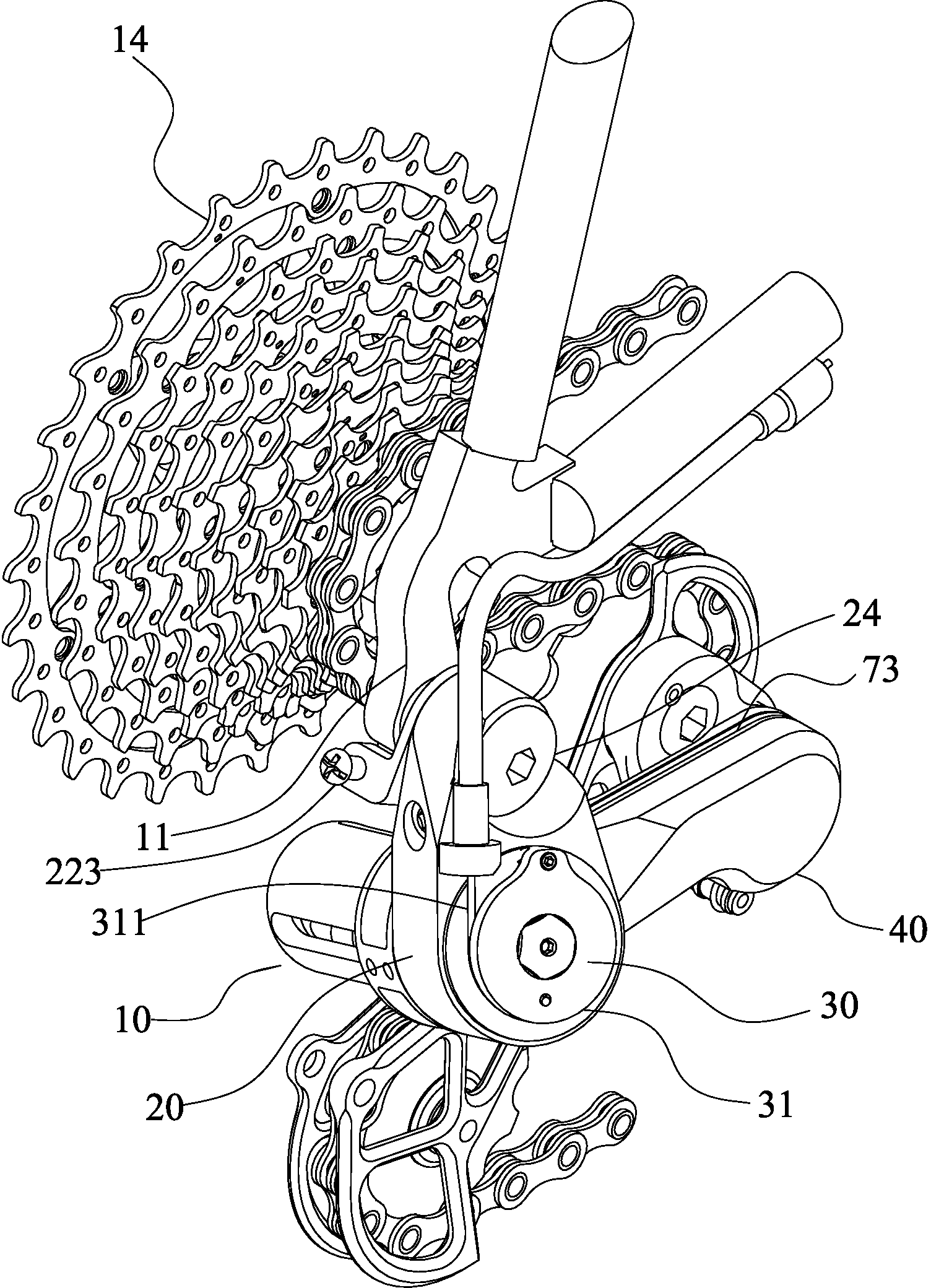
[0056] A rear derailleur 10 of the present invention, the accompanying drawings illustrate a specific embodiment of the present invention, and among its components, all references to front and rear, left and right, top and bottom, upper and lower, and horizontal and vertical are only It is used for convenience of description, and does not limit the invention, nor restrict its components to any position or orientation in space. The dimensions specified in the drawings and description can be changed according to the design and requirements of the specific embodiments of the present invention without departing from the patent scope of the present invention.

[0057] For the detailed structure of rear derailleur 10 of the present invention, please refer to Figure 1 to Figure 10 As shown, the rear derailleur 10 ma...


PUM


Abstract

The invention discloses a rear derailleur used for a bicycle. The rear derailleur is locked on one side of a fork end of a bicycle frame, and contains a screw rod seat, a screw rod, a speed change connecting rod, a bitch chain connecting rod and a connecting rod control line. When a front derailleur pulls or loosens speed change cables, the speed change connecting rod is capable of sliding on the screw rod seat forward and backward; meanwhile a foot end of the connecting rod control line can also pull the bitch chain connecting rod to rotate, change the end point of the bitch chain connecting rod rotating under the action of a return spring, so that the effects of speed change advancing gear, positioning gear, speed change reducing gear and angle positioning of the bitch chain steering wheel can be achieved, the speed change connecting rod and the bitch chain steering wheel cannot rotate to change the positions, and a chain-off phenomenon is avoided; when gear ratio of a flywheel is changed, due to the pulling of the connecting rod control line, the speed change connecting rod can rotate to change the position so as to adjust the angle of the bitch chain steering wheel for tensioning the chain, and the chain-off phenomenon is avoided.

Description

technical field [0001] The invention relates to a rear derailleur for a bicycle. Background technique [0002] As cycling has changed from traditional transportation to sports competition, most people also regard cycling as a way of fitness, so a transmission system is derived, hoping to be able to ride better in different cycling environments Easier and faster. The traditional derailleur system mainly utilizes pulling the derailleur cable to tighten or loosen the derailleur. The connecting rod and spring of the cantilevered rear derailleur drive the moving connecting rod to move, so that the chain engaged on the buckle steering wheel is displaced on the flywheel. , to use different flywheel chainrings, the smaller the gap between the number of teeth between the front large chainring and the rear flywheel, the smaller the pedaling force required; otherwise, a greater force is required. [0003] At present, the rear derailleurs on the market mainly use the cantilever link s...

Claims


Application Information

Patent Timeline
Patent Type & Authority Applications(China)
IPC IPC(8): B62M9/121
Inventor 林昌慧
Owner 林昌慧
Why Eureka
Try Eureka