Low inductance power module

A power module and power technology, applied in the direction of circuits, electrical components, electrical solid devices, etc., can solve the problems of imprecise and expensive

Inactive Publication Date: 2013-05-29
INFINEON TECH AG
View PDF5 Cites 7 Cited by
  • Summary
  • Abstract
  • Description
  • Claims
  • Application Information

AI Technical Summary

Problems solved by technology

However, forming busbars by bending in this form has the disadvantages of being expensive, imprecise, and requiring space to ensure separation distances are met

Method used


Image

  • Low inductance power module
  • Low inductance power module
  • Low inductance power module

Examples


Embodiment Construction

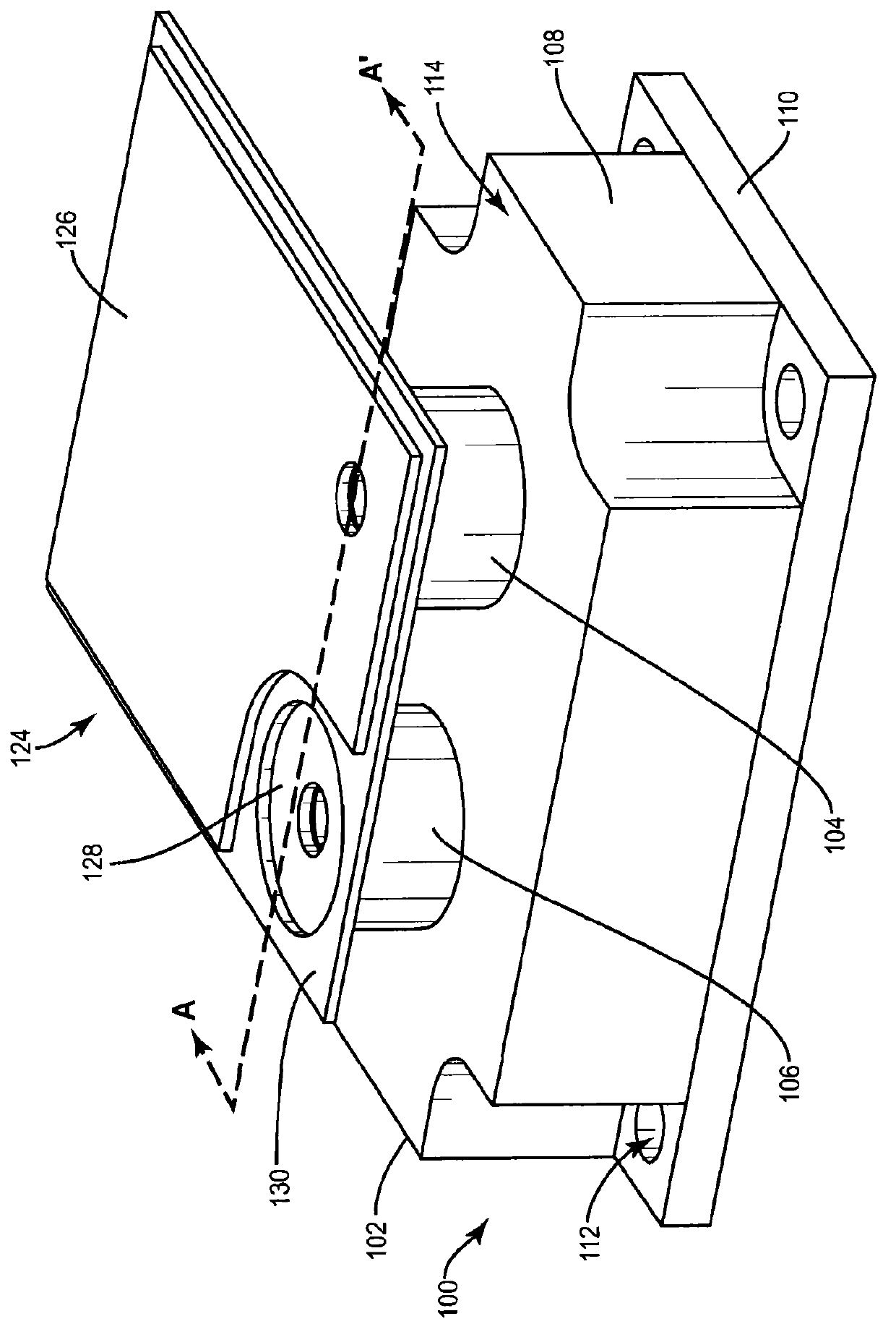
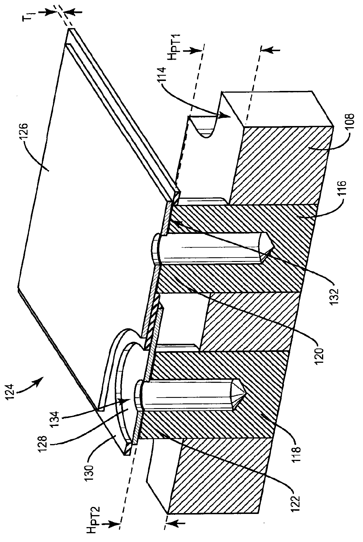
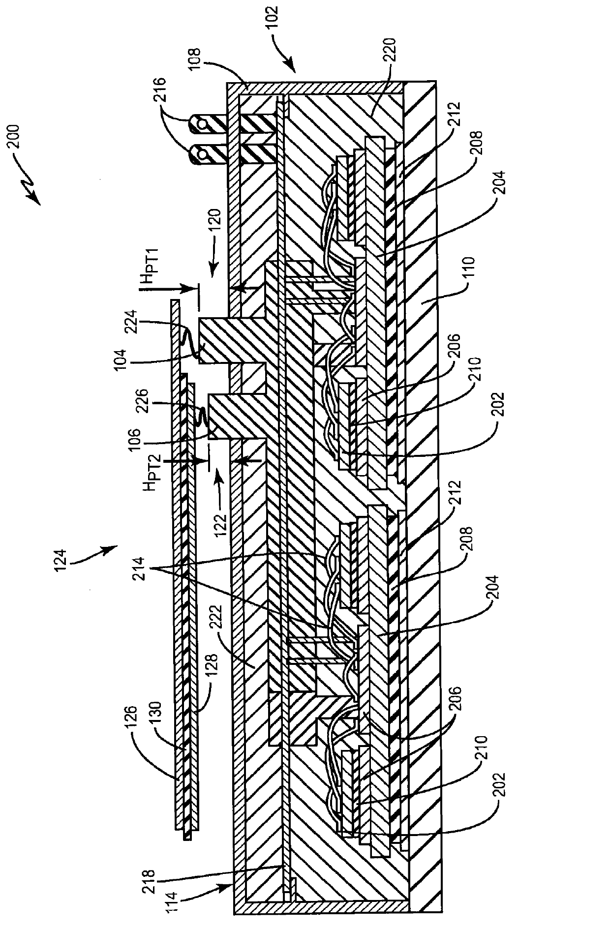
[0014] figure 1 One embodiment of a power module 100 is shown comprising a housing 102 , a power semiconductor die (not visible) enclosed within the housing 102 , a first power terminal 104 and a second power terminal 106 . figure 2 show figure 1 A partial cross-sectional view of the power module 100 shown in , taken along the line marked A-A'. figure 2 Housing 102 and power terminals 104, 106 are shown, but components enclosed by housing 102 are not shown. Exemplary internal components of power module 100 may be described later herein Figure 3-5 was seen in.

[0015] Each power terminal 104 , 106 of the module 100 is embedded in the housing 102 and is electrically connected to a power semiconductor die in the housing 102 . In one embodiment, housing 102 also includes a plastic frame 108 that is attached to metal body 110 . The metal body 110 has a plurality of holes 112 along the periphery for securing the module 100 to, for example, a heating device or other type of ...


PUM


Abstract

The invention refers to a low inductance power module. A power module includes a housing, a power semiconductor die enclosed within the housing and a first power terminal embedded in the housing and electrically connected to the power semiconductor die. A portion of the first power terminal protrudes outward from an external surface of the housing. The power module further includes a second power terminal embedded in the housing and electrically connected to the power semiconductor die and electrically insulated from the first power terminal. A portion of the second power terminal protrudes outward from the external surface of the housing by a distance less than the portion of the first power terminal so that the module has power connections with different heights.

Description

technical field [0001] The present application relates to power modules, especially power modules with low inductance power terminals. Background technique [0002] When designing a low-cost power module, it is common to use as few components as possible. One easily reproducible component required to manufacture a power module is the contacts for the power connections. Traditional power module designs have power connections located within the module and protruding outward from the module at the same fixed height for easy handling. For example, the positive (+) and negative (-) DC supply terminals of a power module have the same height by convention. The external electrical connector is provided with corresponding bus bars for connection to the power terminals of the module. To ensure a low inductance design, the positive busbar of the external connector is usually placed on top of the negative busbar, with insulating material separating the busbars from each other. Since...

Claims


Application Information

Patent Timeline
Patent Type & Authority Applications(China)
IPC IPC(8): H01L25/00H01L23/48H01R25/16
CPCH01L23/24H01L2224/48472H01L2224/73265H01L23/3735H01L2224/32225H01L25/07H01L2924/13091H01L23/049H01L2224/48227H01L23/49811H01L2924/30107H01L2924/13055H01L23/48H01L25/072H01L2924/1305H01L2924/13062H01L2924/181H01L2924/19107H05K7/14329H01L2924/00H01L2924/00012H05K7/1432
Inventor A·克罗斯特曼P·琼斯
Owner INFINEON TECH AG
Why Eureka
Try Eureka