Face massager

A massager and facial technology, applied in the field of facial pressure massagers, can solve problems such as inconvenience of use, difficulty in expecting facial correction effects, etc., and achieve the effects of stable wearing and use status and relieving facial pain.

Inactive Publication Date: 2013-06-05
金相秀
View PDF3 Cites 10 Cited by
  • Summary
  • Abstract
  • Description
  • Claims
  • Application Information

AI Technical Summary

Problems solved by technology

[0006] But above-mentioned prior art 2 is the same as above-mentioned prior art 1, all is the structure that compresses user's face and occipital region, and only the end portion of above-mentioned massage protrusion is in contact with user's face, therefore, it is difficult to expect Facial correction effect
In addition, when the user wears it, the main body and the branches will block the user's nose and mouth, so it is not convenient to use

Method used


Image

  • Face massager
  • Face massager
  • Face massager

Examples


Embodiment Construction

[0056] The advantages, features and implementation methods of the present invention will be described in detail in the following embodiments with reference to the accompanying drawings. However, the following examples do not limit the scope of the present invention, and it may have various forms different from each other.

[0057] Hereinafter, technical features of the present invention will be specifically described with reference to the accompanying drawings.

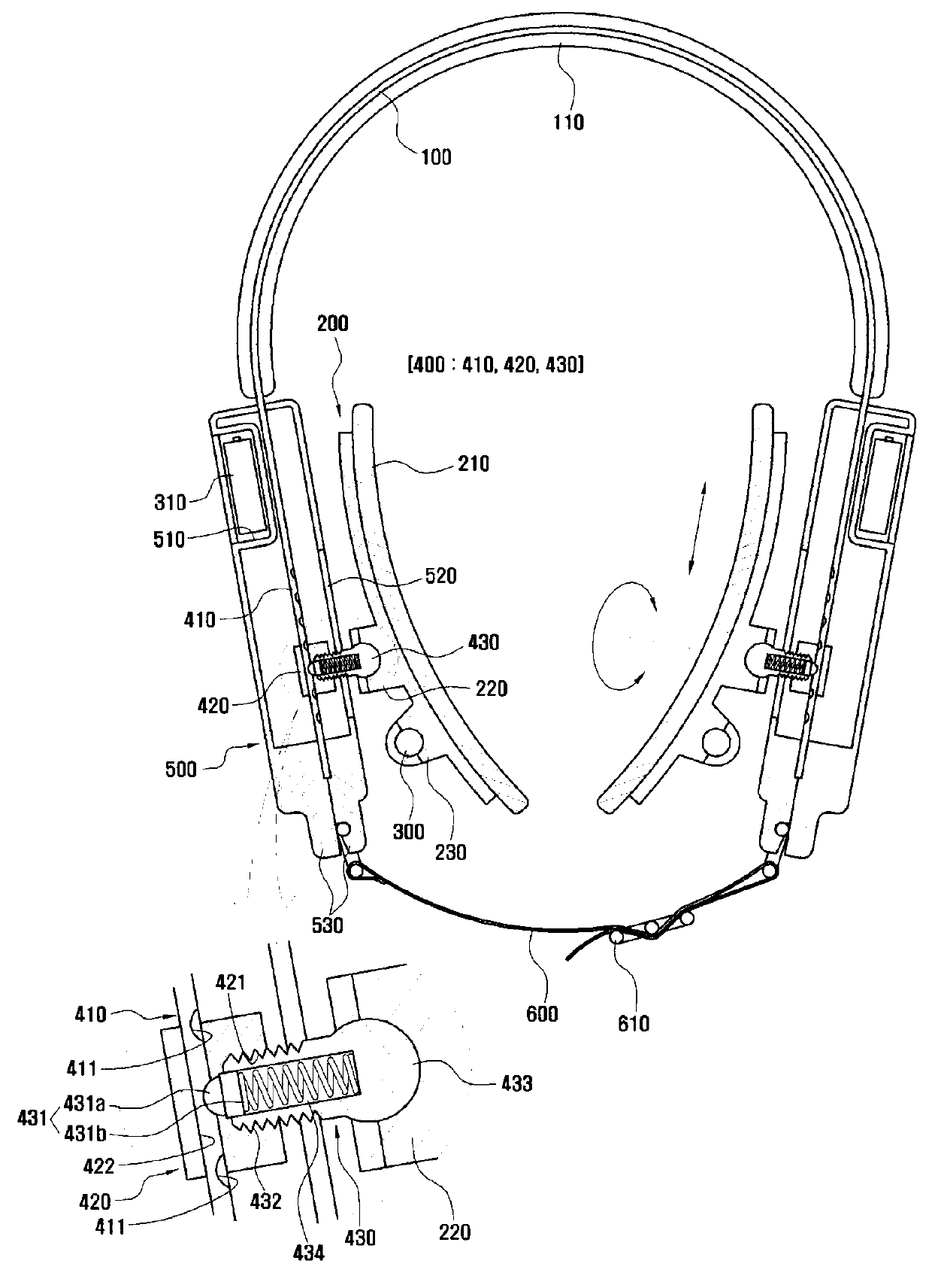
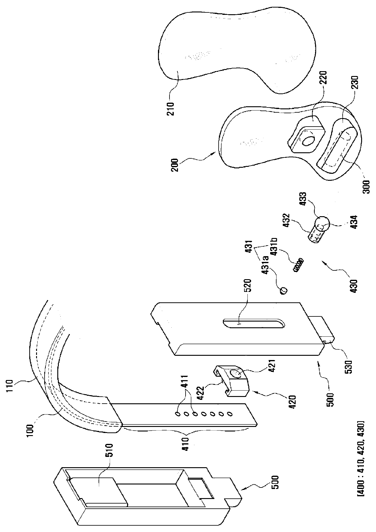
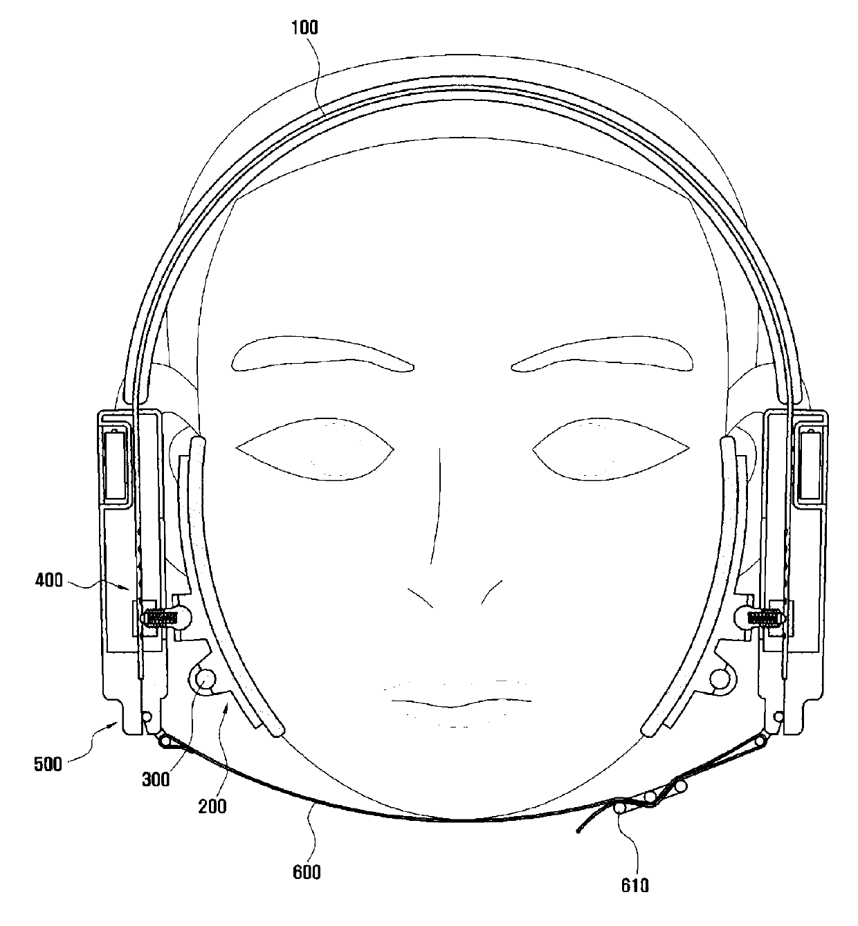
[0058] figure 1 It is a sectional view shown for explaining the structure of the facial pressure massager according to the embodiment of the present invention, figure 2 is showing figure 1 An exploded perspective view of the facial compression massager shown, image 3 It is a schematic diagram showing the wearing state of the facial pressure massager according to the present invention.

[0059] Such as Figure 1 to Figure 3 As shown in , the facial pressure massager according to the embodiment of the present inv...


PUM


Abstract

A pressurized facial massager machine comprises an elastic frame worn on the head of a user and a platen mounted on two end parts of the elastic frame, thereby pressurizing and correcting the faces of the user from two sides.

Description

technical field [0001] The present invention relates to a massager, in particular, to a facial pressure massager, which is composed of an elastic frame worn on the user's head and pressure plates installed at both ends thereof, so that it can be used from both sides Correction with pressure on the patient's face. Background technique [0002] Under normal circumstances, the purpose of massaging the face is to prevent facial skin from aging or to relieve skin fatigue and prevent it from becoming rough. In particular, for women, the aging of the skin is accelerated due to stress on the facial skin due to make-up, etc., and the frequently exposed facial skin is prone to dark spots or cracks due to ultraviolet radiation due to environmental changes. It is precisely because female friends are particularly concerned about this phenomenon that a large number of devices or instruments that only massage the face have been developed. [0003] Regarding the existing facial pressure m...

Claims


Application Information

Patent Timeline
Patent Type & Authority Applications(China)
IPC IPC(8): A61H23/02A45D44/22
CPCA45D44/22A45D2200/207A61H23/02A61H2201/1207A61H2201/1607A61H2205/022
Inventor 金相秀
Owner 金相秀
Why Eureka
Try Eureka