
Image distortion correction method and real-time correction device based on conic section

A conic curve and image distortion technology, applied in the field of image processing, can solve problems such as high CPU performance requirements, complex algorithms, and dependence on lens parameters, and achieve the effect of reducing configuration requirements and simple calculations

Active Publication Date: 2018-12-18
石家庄域联视控控制技术有限公司
View PDF6 Cites 0 Cited by
  • Summary
  • Abstract
  • Description
  • Claims
  • Application Information

AI Technical Summary

Problems solved by technology

[0005] The Chinese patent application "A Calibration Method and Calibration Device for Radial Distortion of Fisheye Lens" (Application No.: 201410244246.3) discloses a method for fitting the distortion using a group of collinear arcs with centers of circles. CPU performance requirements are high; the Chinese patent application "A Method and Device for Correcting Image Barrel Distortion" (Application No.: 201510019338.6) discloses a method that determines the curvature and compression rate at the coordinates according to the lens parameters and pixel coordinates, Then the coordinate point after the pixel coordinate correction is obtained
This method depends on the lens parameters and can only correct the barrel distortion of the image

Method used


Image

  • Image distortion correction method and real-time correction device based on conic section
  • Image distortion correction method and real-time correction device based on conic section
  • Image distortion correction method and real-time correction device based on conic section

Examples


Embodiment Construction

[0042] The present invention includes two parts: 1. the calibration process of the lens and 2. the real-time correction process.

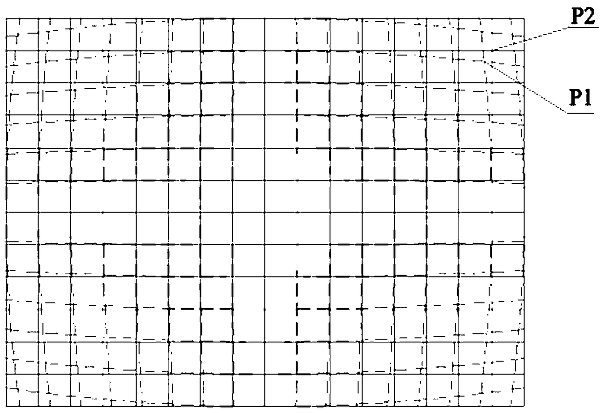
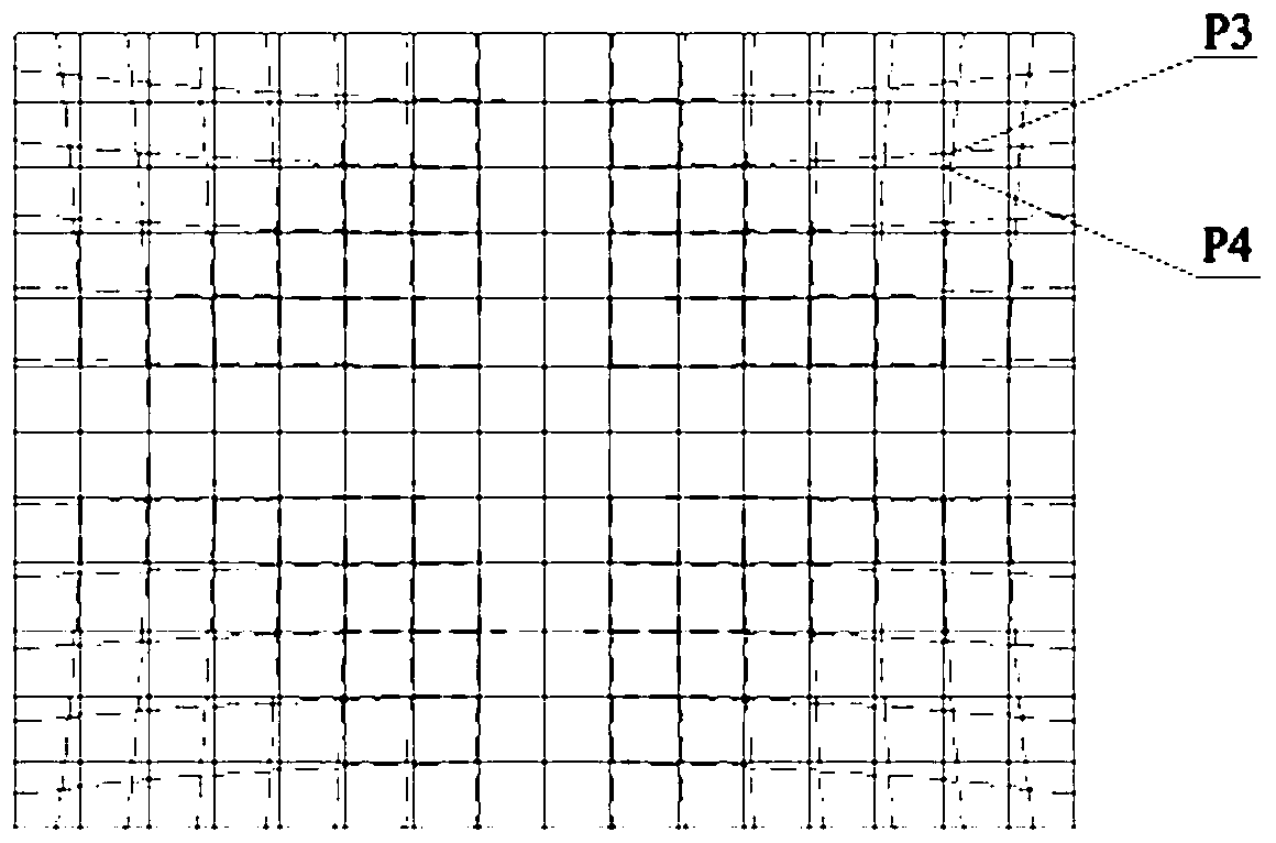
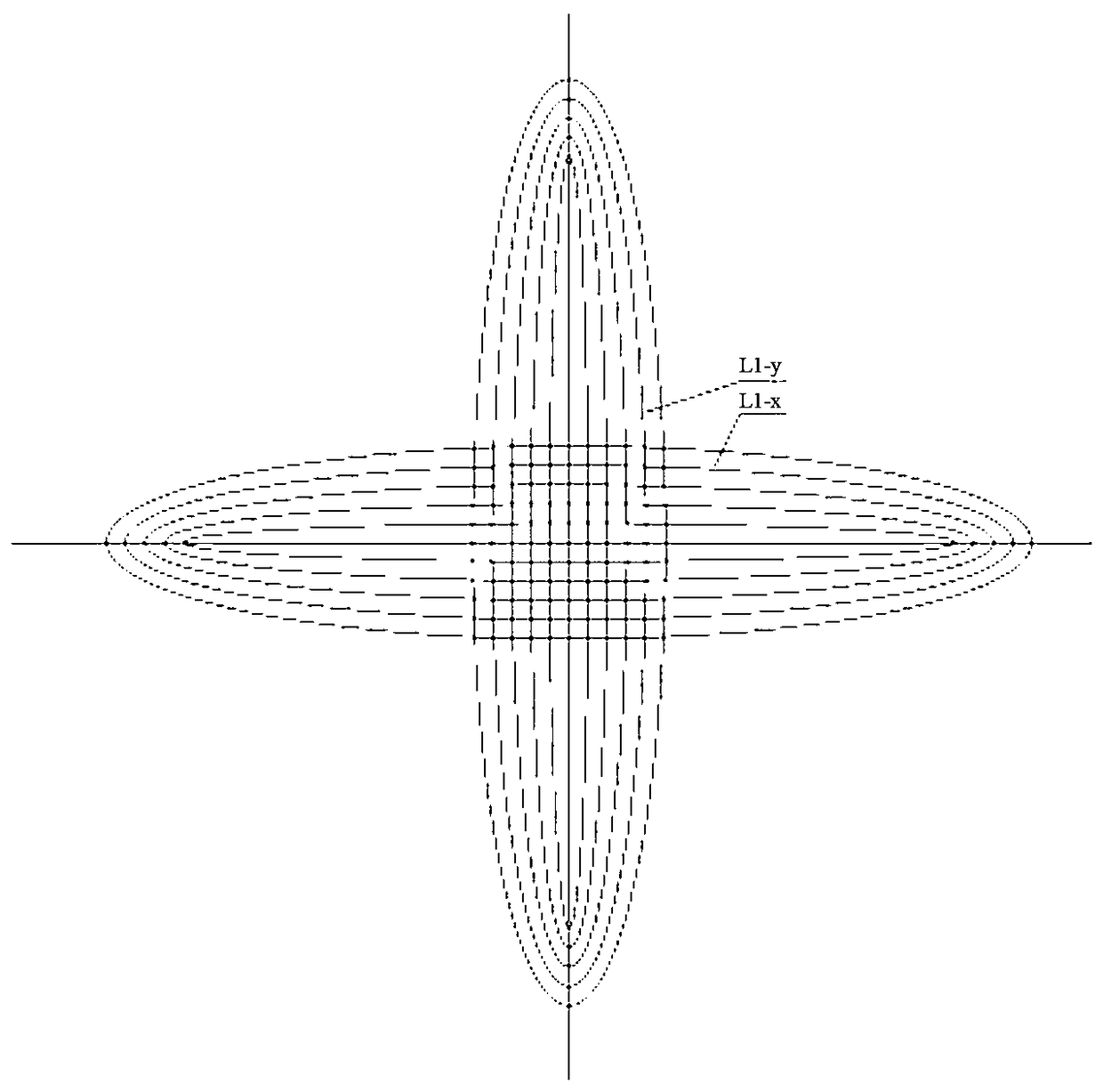
[0043] Such as Figure 10 As shown, the calibration process of the lens is to first obtain a photo with a grid picture, judge the distortion type according to the distortion line on the photo, and then obtain the conic curve equation, and then calculate the coordinate values ​​of each point on the deformation line according to the curve equation, and finally The corresponding relationship between the distorted image and the pixels of the rectified image is calculated.

[0044] Write the corresponding relationship obtained into the CPU of the embedded system. When the embedded system is working, a real-time correction process is performed, such as Figure 11 As shown, the distorted image is obtained first, and then the corresponding relationship is read. According to the corresponding relationship, the pixel information and the converted position i...


PUM


Abstract

The invention relates to an image distortion correction method based on a conic curve and a real-time correction device, and belongs to the technical field of image processing. In particular, the invention relates to an image distortion correction method based on a conic curve and a device for real-time correction of an image using the method, which uses an ellipse or hyperbolic equation for simulating image distortion and is achieved in an embedded system. First of all, a lens is calibrated, and then in accordance with the calibration result, a distorted image is corrected in real-time. The method comprises a first step of obtaining a photograph with a grid pattern picture; a second step establishing a plane rectangular coordinate system; a third step of judging the image distortion type according to the photograph; a fourth step of obtaining an approximate conic curve equation of a deformation line; and a fifth step of obtaining a corresponding relation between the distorted image and the corrected image pixel point. The corresponding relation is written into a CPU of the embedded system. In operation, the CPU reads the pixel information of the distorted image, and according to the corresponding relation, converts the position and writes into the corrected image file. The invention can be used for reducing the configuration requirement of the CPU while maximizing the correction of the image to obtain an acceptable corrected image.

Description

technical field [0001] The invention belongs to the technical field of image processing, and in particular relates to a conic section-based image distortion correction method and a device for real-time image correction using the method. Background technique [0002] At present, in the field of surveillance, in order to meet the needs of different situations, different types of lenses need to be used. The general lens has a certain degree of optical distortion in the imaging process, which causes some changes in the size and shape of the imaging image, and the quality of the image decreases, which will bring errors to the subsequent image analysis and image measurement, and even cause misjudgment. Therefore, it is necessary to correct the geometric distortion of the image caused by the camera lens. [0003] Depending on the lens, the possible distortions fall into two categories: barrel distortion and pincushion distortion. [0004] The correction algorithms for nonlinear d...

Claims


Application Information

Patent Timeline
Patent Type & Authority Patents(China)
IPC IPC(8): G06T5/00
CPCG06T5/006
Inventor 罗启宏曹晶赵青波熊炜胡春美苗俊峰
Owner 石家庄域联视控控制技术有限公司
Learn More