A bending mechanism of a bending machine

A bending mechanism and bending machine technology, applied in the field of bending machines, can solve problems such as time-consuming and affecting bending efficiency, and achieve the effects of reducing friction, improving workpiece quality, and facilitating reset

Active Publication Date: 2016-05-18
JDM JINGDA MASCH (NINGBO) CO LTD
View PDF8 Cites 0 Cited by
  • Summary
  • Abstract
  • Description
  • Claims
  • Application Information

AI Technical Summary

Problems solved by technology

[0003] The existing heat exchanger workpiece bending process is to place it horizontally on the worktable for bending, and the feeding device releases the workpiece during bending, and then clamps the workpiece to feed after a bending is completed, and then Carrying out the second bending, it takes a certain amount of time to clamp and then loosen, resulting in a longer working cycle, which affects the bending efficiency, especially on workpieces with a large number of bending times.
Moreover, there are many types of heat exchanger workpieces, and the existing bending mechanism cannot adapt to this situation

Method used


Image

  • A bending mechanism of a bending machine
  • A bending mechanism of a bending machine
  • A bending mechanism of a bending machine

Examples


Embodiment Construction

[0032] The present invention will be further described in detail below in conjunction with the accompanying drawings and embodiments.

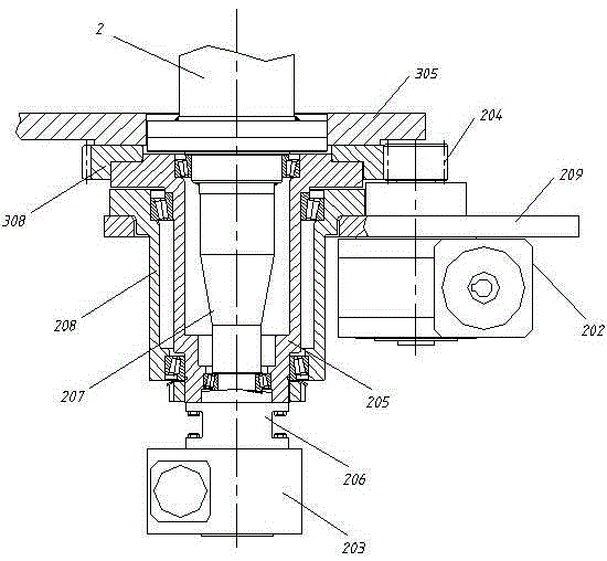
[0033] Such as figure 1 As shown, in the bending mechanism of the bending machine, the bending die rotation mechanism is the first servo motor 203 with the first reducer, and the bending die 2 is installed at the end of the first reducer output shaft 207 of the first servo motor 203, and the output The shaft 207 is supported by bearings in the bending die sleeve 205, and the first servo motor 203 is fixed on the bending die sleeve 205 through the connecting flange 206, so the first servo motor 203 can independently drive the shaft out of the shaft 207 to rotate, thereby driving the fixed The bending die 2 on the output shaft 207 rotates, but the bending die bushing 205 does not rotate, that is, the binder plate does not rotate.

[0034] The binder plate rotating mechanism includes a second servo motor 202 with a second reducer, the second ser...


PUM


Abstract

A bending mechanism of a bending machine comprises a pressure plate, a pressure plate rotating piece, a pressure plate rotating mechanism driving the pressure plate rotating piece to rotate, a bending mold device and a bending mold rotating mechanism driving the bending mold device to rotate. The pressure plate is connected with the pressure plate rotating piece, a rotating center of a bending mold is connected onto the pressure plate rotating piece through a bearing, the bending mold rotating mechanism is fixed on the pressure plate rotating piece, and the pressure plate is parallel to a bending mold plate of the bending mold device. The bending mechanism can bend workpieces of various forms conveniently and efficiently.

Description

technical field [0001] The invention relates to a bending machine, in particular to a bending mechanism of the bending machine. Background technique [0002] The bending machine is used to bend the heat exchanger into a G shape, U shape or L shape. It is the key equipment for forming the heat exchanger, and the bending mechanism is the main part of the bending machine. [0003] The existing heat exchanger workpiece bending process is to place it horizontally on the worktable for bending, and the feeding device releases the workpiece during bending, and then clamps the workpiece to feed after a bending is completed, and then For the second bending, it takes a certain amount of time to clamp and then loosen, resulting in a longer working cycle, which affects the bending efficiency, especially on workpieces with more bending times. Moreover, there are many types of heat exchanger workpieces, and the existing bending mechanism cannot adapt to this situation. Contents of the i...

Claims


Application Information

Patent Timeline
Patent Type & Authority Patents(China)
IPC IPC(8): B21D11/00B21D53/02
Inventor 刘险峰章闰郑良才
Owner JDM JINGDA MASCH (NINGBO) CO LTD
Why Eureka
Try Eureka