Reinforcement steel bar no-twist straightening shearing machine

A shearing machine and steel bar technology, applied in the field of steel bar twist-free straightening and shearing machine, can solve the problems that the steel bar cannot be prevented from twisting, the steel bar structure is complicated, and the adjustment is inconvenient, etc., and the structure is simple, straightening and shearing speed are fast , Adjust the effect of convenience

Inactive Publication Date: 2013-06-05
广西国盾人防工程有限公司
View PDF7 Cites 2 Cited by
  • Summary
  • Abstract
  • Description
  • Claims
  • Application Information

AI Technical Summary

Problems solved by technology

[0003] In order to solve the problems of complex structure of existing steel bars, inconvenient adjustment and inability to prevent the torsion of steel bars, The technical problem to be solved by the present invention is to provide a non-twist straightening and shearing machine for steel bars, which has fast straightening and shearing speed, simple structure, convenient adjustment, prevents the twisting of steel bars at the same time, and greatly reduces production costs

Method used


Image

  • Reinforcement steel bar no-twist straightening shearing machine
  • Reinforcement steel bar no-twist straightening shearing machine
  • Reinforcement steel bar no-twist straightening shearing machine

Examples


Embodiment Construction

[0025] Below in conjunction with accompanying drawing, further illustrate structure of the present invention and use state:

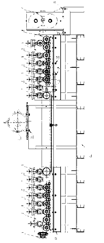
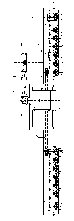
[0026] see figure 1 with Figure 1A , the rigid rib non-twist straightening and shearing machine includes a frame 21, a guiding and limiting device 1, a straightening assembly 2, a motor 3, a reducer 4, a traction assembly 5 and a shearing assembly 6. The straightening assembly 2 is fixed on the frame 21 through connecting bolts 10, the guide and stop device 1 is welded and fixed on the front end of the straightening assembly 2, the traction assembly 5 and the shearing assembly 6 are respectively fixed through connecting bolts 12 and 22 On the frame 21, and in turn located behind the straightening assembly 2. The distance between the straightening assembly 2 and the traction assembly 5 is more than 10cm, so that the reinforcement can be extended better. The motor 3 is arranged between the straightening assembly 2 and the traction assembly 5 through c...


PUM


Abstract

A reinforcement steel bar no-twist straightening shearing machine comprises a straightening assembly, a dragging assembly, a shearing assembly and a dynamic assembly. The straightening assembly is arranged before the dragging assembly, the shearing assembly is arranged after the dragging assembly, and the dynamic assembly is arranged between the straightening assembly and the dragging assembly. The dragging assembly is provided with a dragging wheel set and an acceleration chain wheel, wherein the dragging wheel set is connected with the output end of the dynamic assembly, and the acceleration chain wheel is driven by the dragging wheel set. The straightening assembly is provided with a deceleration chain wheel and an aligning wheel set, wherein the deceleration wheel is connected with the acceleration chain wheel of the dragging assembly, the straightening assembly is driven by the deceleration chain wheel, and the number of teeth of the deceleration chain wheel is larger than that of the acceleration chain wheel. The dragging wheel set and the straightening wheel set both are provided with a plurality of pairs of plane anti-twist wheels and groove location wheels, wherein the plurality of pairs of plane anti-twist wheels and groove location wheels are arranged at intervals, an outer circle of each plane anti-twist wheel is a smooth cylindrical surface, a rectangular narrow slit used for passage of a reinforcement steel bar is formed between each pair of plane anti-twist wheels and prevents the reinforcement steel bar from twisting. An outer circle of each groove location wheel is a cylindrical surface with an annular groove, and a circular channel is formed between each pair of groove location wheels and used for passage of the reinforcement steel bar and locating the reinforcement steel bar. The reinforcement steel bar no-twist straightening shearing machine utilizes the speed difference between the straightening assembly and the dragging assembly to enable the reinforcement steel bar to generate plastic deformation, and therefore the purpose of straightening the reinforcement steel bar is achieved.

Description

technical field [0001] The invention relates to straightening equipment for steel bars, in particular to a non-twist straightening and shearing machine for steel bars. Background technique [0002] With the rapid development of the construction industry and construction technology, the requirements for steel bars are becoming more and more stringent, especially the performance requirements, which are particularly important. Steel bar straightening is the main means to improve the performance of steel bars, but the steel bar straightening and shearing equipment currently on the market mainly adopts the straightening method of swinging barrels and the straightening method of horizontal and vertical two-way wave curves. The straightening method of horizontal and vertical two-way wave curves is faster, but the structure is complex, the adjustment is inconvenient, and the twisting of the steel bars cannot be prevented, which will have a certain impact on the appearance of the pro...

Claims


Application Information

Patent Timeline
Patent Type & Authority Applications(China)
IPC IPC(8): B21F1/02B21F11/00B21F23/00
Inventor 薛志远杜飞
Owner 广西国盾人防工程有限公司
Why Eureka
Try Eureka